"
Subjectives:
sibilance
listener fatigue ('edginess')
mid and top end clarity
image focus, ability to define spatially the exact location of an instrument or vocalist
front to back imaging, including depth
left to right imaging, including width
euphony - if the amp is 'musical' or not
These words are the darlings of some audiophile reviewers who inform the market, but they are necessary if we are to assess the sound without lapsing in technical vernacular which may not have any obvious link to the listening experience. And they are commercially higly relevant since people, right or wrong, often buy on the strength of reviews."
Hugh, I believe that it s the recroding quality that affects the above 50% and the speaker/listening room 49%. The amp and pre-amp combo might contribute 1%, assuming threy are well engineered.
1k and 10K (2V input).
AX is the standard "blameless" (Bode att. 1)
GX is the big amp (120v p/p) (Bode att.2)
Ax has over 100db gain , it is the one that sounds sterile (but good) , and does not even show a couple mV between bases until you go "nuclear" at over 100v p/p.
The GX only has half the gain but sounds nicer in general , it deviates up to 20+ mV when "pushed". So , the "cause and effect" holds true between OLG and the differential. I've never tested this before. Both are stable , run basically the same NFB network , only differ in loop gain.
OS
Ostripper, those are O/L plots. Lets take a look at the loop gain plots - gain and phase. They might reveal something more.
but what is the differential voltage at the input with a fast starting transient? I suspect it is very much higher. Leach shows us why it is higher.BTW , I know on the simple bootstrap amps .. I have measured close to a volt between bases on the differential. I just measured my GX (luxman) , just under 20mv for 130v p/p. confirmed on the real thing. All my "new" amps show nearly nothing (<5mV) as far as voltage differences between base voltages.
That is why we fit input filtering.
but what is the differential voltage at the input with a fast starting transient? I suspect it is very much higher. Leach shows us why it is higher.
That is why we fit input filtering.
I would need to "scope" that. I have seen ,even on the "fast" amps, a delay (input wave delayed before NFB wave) on my dual trace scope.
My test setup was simplistic , a DMM and test tones (1 /10K) on a USB 4Gb portable MP3 player. 😱
OS
Ax has over 100db gain , it is the one that sounds sterile (but good)
I am starting to think that the closer you get to my ideal amp (straight wire with gain) the more "sterile" it will sound and that most audiophiles, like recording engineers prefer a small amount of a certain type of distortion(s). (the Neve post earlier).
CBDB,
I agree emphatically, this is my experience utterly.
Rupert Neve, in his early consoles, used high voltages (100V+) and all single ended circuitry to promote even order artefacts. These consoles are much revered, just as you say.
People talk reds, but drink white.....
Hugh
I agree emphatically, this is my experience utterly.
Rupert Neve, in his early consoles, used high voltages (100V+) and all single ended circuitry to promote even order artefacts. These consoles are much revered, just as you say.
People talk reds, but drink white.....
Hugh
Rupert Neve, in his early consoles, used high voltages (100V+)
Talk about headroom!
Hello
Looking in some other VAS I've seen this one, anyone know the pros and cons of this VAS ?
Thank
Bye
Gaetan
Looking in some other VAS I've seen this one, anyone know the pros and cons of this VAS ?
Thank
Bye
Gaetan
Attachments
Last edited:
Hi
Talking of limiter
Is it a vas Baker Clamp, if not, how does it look like and how does it work ?
Thanx
Paul
Talking of limiter
Is it a vas Baker Clamp, if not, how does it look like and how does it work ?
Thanx
Paul
Last edited:
Gaetan,
It might be better to put the limiter on the collector rather than the emitter side, still measuring current, but set to a ridiculous current well short of the max collector current but much higher than the VAS operating current.
If you place it on the drive (base) side, there will be a transition zone of activation which could affect the sound quality.
Hugh
Hello Hugh
I was not sure about this VAS, usually I don't use a current limiter in a VAS, so I did asked for the pros and cons of it.
Btw, I've just look in all my amps schematics and this VAS was coming from a Leach amp, the image I've post was the VAS alone (no amp schema) from a web site.
Thank
Bye
Gaetan
I was not sure about this VAS, usually I don't use a current limiter in a VAS, so I did asked for the pros and cons of it.
Btw, I've just look in all my amps schematics and this VAS was coming from a Leach amp, the image I've post was the VAS alone (no amp schema) from a web site.
Thank
Bye
Gaetan
Last edited:
The Leach and similar amps that have current and/or IV limiting on the output stage can overload the VAS when the limiting activates.
The extra transistor is there to prevent the VAS being driven to destruction by the LTP trying to force the VAS to drive the current limited output stage when it is already overloaded.
The sum of the two resistor is the required degeneration that the VAS needs.
The BE resistor should be sized to drop ~2/3 Vbe (~400mV) when the VAS is passing ~ two times it's bias current.
If VAS Ib=10mA then VAS can go from 0mA to 20mA and not be overloaded. When running at upto this range of currents the Protection transistor must not interfere with the VAS feed from the LTP. If the lower resistor is 20r then 20mA of maximum VAS peak output current produces a Vbe of 400mV. The protection transistor will be fully active when the VAS current rises to ~30mA (~3times Iq).
Hello
I know that there is different opinions about the listening result of a cascoded VAS in a amp.
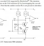
But can we use a Hawksford cascoded VAS, without a buffer transistor, with low power amp (up to 40 watt) ?
I just want to know more about it.
Here is an image of a Hawksford cascoded VAS with a very little mod. I could use this one with a 30 watt amp ?
Thank
Happy New Year
Bye
Gaetan
I know that there is different opinions about the listening result of a cascoded VAS in a amp.
But can we use a Hawksford cascoded VAS, without a buffer transistor, with low power amp (up to 40 watt) ?
I just want to know more about it.
Here is an image of a Hawksford cascoded VAS with a very little mod. I could use this one with a 30 watt amp ?
Thank
Happy New Year
Bye
Gaetan
Attachments
Last edited:

...a Hawksford cascoded VAS with a very little mod.
Hi Gaetan
That "very little mod" completely defeats the point of the Hawksford cascode.
Have you read the Hawksford article itself?
Worth some effort even if it's written a bit obscurely.
Personally I find it easier to understand as an internal feedback loop, but perhaps that's just me.
Best wishes
David
Hawksford cascoded VAS I show in my image are from the book of Douglas Self, and my "very little mod" are just adding the 10 R resistor (the magic resistor suggested by Peufeu in his web site).
Thank
Bye
Gaetan
Thank
Bye
Gaetan
Hi Gaetan
That "very little mod" completely defeats the point of the Hawksford cascode.
Have you read the Hawksford article itself?
Worth some effort even if it's written a bit obscurely.
Personally I find it easier to understand as an internal feedback loop, but perhaps that's just me.
Best wishes
David
Hello
Can you email me this article ?
gaetan888 at gmail dot com
Thank
Bye
Gaetan
Hawksford cascoded VAS... from the book of Douglas Self...
What edition is your book?
I have the 5th edition (Focal Press) and there is an emitter resistor for Q1.
That resistor is essential to make it a "Hawksford" cascode, as opposed to just a cascode.
It looked that you had removed this resistor for your "very little mod" but it seems D.Self or the book publisher messed this up.
Best wishes
David
Paper is here. http://www.aes.org/e-lib/browse.cfm?elib=5157
Last edited:
Hawksford "Slope Distortion" paper:
https://web.archive.org/web/2013012..._lab/malcolmspubdocs/J10 Enhanced cascode.pdf
https://web.archive.org/web/2013012..._lab/malcolmspubdocs/J10 Enhanced cascode.pdf
- Status
- Not open for further replies.
- Home
- Amplifiers
- Solid State
- What are the pros and the cons of those 3 vas ?