They will be heated by all those around them. Quoted dissipation assumes free air. Even the ones on the edge will not meet the full spec, except for short periods.
Yep it's true, my 4x7 array of closely spaced 10W resistors won't be able to dissipate 4x7x10 = 280W in still air for very long. Which is why I used the time honored professional circuit design algorithm called Rectal Extraction to derate it back to 150W in the title of this thread. As Ed Simon points out in post #7 above, forced air will help somewhat. Maybe my pals at NASA Ames can score me a half gallon of Fluorinert from one of their Cray-2 cooling baths. That'd help too.
But perhaps the cheapest and most obvious fixup is to go to a bigger array with greater margin-of-safety. Instead of 28 10 watt resistors why not have 40 10 watt resistors? And while we're covering our behind let's pack the resistors at looser layout pitch too. It's only money and it's not much money either.
But perhaps the cheapest and most obvious fixup is to go to a bigger array with greater margin-of-safety. Instead of 28 10 watt resistors why not have 40 10 watt resistors? And while we're covering our behind let's pack the resistors at looser layout pitch too. It's only money and it's not much money either.
Yes, two things help:
1. some space - the more the better, so air can flow
2. some time - the less the better, so you take advantage of thermal mass
1. some space - the more the better, so air can flow
2. some time - the less the better, so you take advantage of thermal mass
forced air cooling and more spacing allowing better passive cooling will allow the resistive element to run hotter. Tempco will not be zero. There will be a change in resistance if temperatures change.
More Thermal mass in the resistive elements that have an acceptable tempco seems to me to be the way to go.
More Thermal mass in the resistive elements that have an acceptable tempco seems to me to be the way to go.
The thermal coefficient for a typical wire wound resistor is 350PPM. At full power rating the temperature rise is 210C. The highest melting point of a typical lead free solder is 222C. Eutetic is 183C.
So just before everything melts the change in resistance would be about half an ohm. So if that were a critical issue one could play with an NTC resistor to compensate.
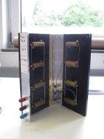
In my experience the power limit is determined by the solder melting. In the design shown here there is some heat sinking to the solder joints.
With fan cooling and a surrounding tunnel you could quite possibly get 20 watts out of a ten watt cement resistor. The nichrome wire, the Leads and their crimp will all take a lot of heat.
Then Mark has enough parts to build a few of these, so the actual limit may be the power from his AC line source!
So just before everything melts the change in resistance would be about half an ohm. So if that were a critical issue one could play with an NTC resistor to compensate.
In my experience the power limit is determined by the solder melting. In the design shown here there is some heat sinking to the solder joints.
With fan cooling and a surrounding tunnel you could quite possibly get 20 watts out of a ten watt cement resistor. The nichrome wire, the Leads and their crimp will all take a lot of heat.
Then Mark has enough parts to build a few of these, so the actual limit may be the power from his AC line source!
Last edited:
While it is fun to roll your own, one wonders if it is always practical?
1/2/4/8/10 Ohm 100W Watt Shell Power Aluminum Housed Case Wirewound Resistor
1/2/4/8/10 Ohm 100W Watt Shell Power Aluminum Housed Case Wirewound Resistor
Tony,
Where did you get this?
from china....https://www.aliexpress.com/item/8-o...dio-Amplifier-Dummy-Load-100W/2021450412.html

Neat solution!
Use normal cooking oil instead - then when you can smell popcorn, turn it down a bit 😀
/U.
Putting the stack in a jar of engine oil would work for at least 10s of minutes
Use normal cooking oil instead - then when you can smell popcorn, turn it down a bit 😀
/U.
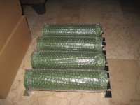
electric water heater elements
https://www.youtube.com/watch?v=5gAUuLkc1ik
https://www.youtube.com/watch?v=TWwHJBFkKMY
https://www.youtube.com/watch?v=5gAUuLkc1ik
https://www.youtube.com/watch?v=TWwHJBFkKMY
From memory these are 32 R and have a useful half way tap to give 8R. Could be the way it's made will keep inductance low used as 8R. The 16R and 32R will be useful also. As these run at 1600 watts with a fan 150 watts should be OK in free air.
https://www.amazon.co.uk/BOSCH-NEFF...coding=UTF8&psc=1&refRID=N6M64Z4PZE6J1RKNJ2XE
https://www.amazon.co.uk/BOSCH-NEFF...coding=UTF8&psc=1&refRID=N6M64Z4PZE6J1RKNJ2XE
Nigel,
do you know the power and resistance of these "oven heater elements"?
P=240² / 32 = 1800W ? or 230² / 32 = 1653W ?
Do you know what their cold resistance is?
do you know the power and resistance of these "oven heater elements"?
P=240² / 32 = 1800W ? or 230² / 32 = 1653W ?
Do you know what their cold resistance is?
All I rememeber Andrew is they are circa 1600 watts at 230 V. They are at best +/- 10% I suspect. When sine wave testing 7R5 to 8R5 suits me fine. I do remember the one I checked before installing it as bang on 32R cold. When hot it can't be too different as the rated power is 1600W.
Looks like each half @ 16r would make a reasonable 225W load for operation upto 60Vac.
or 450W wired as a pair for 8r.
or 450W wired as a pair for 8r.
I built another unit today and this time I remembered to snap all scope photos at the same sweep rate! (see post #7 above).
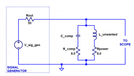
As a reminder, the goal is to construct a high wattage, noninductive, 8 ohm resistor using inexpensive 10W wirewound components (which are themselves, quite inductive). The resulting circuit is a factor of 10X to 20X less expensive than the exotic Ayrton-Perry type of noninductive resistor, see post #13.
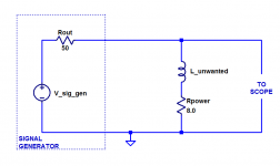
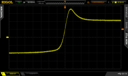
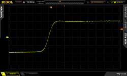
I use square wave testing to observe the inductive behavior of these resistors, as Elvee did in post #3. The test setup is shown in Figure 1 below. A signal generator produces square waves, which are applied to the inductive 8 ohm resistor at right, and an oscilloscope monitors the waveshape. The inductive reactance of L_unwanted allows the leading edge and trailing edge of the square wave to overshoot, shown in Figure 2.
(Notice that the signal generator's 50 ohm output impedance, forms a voltage divider with the 8 ohm load)
Then I add the compensator network (R_comp and C_comp) in parallel with the power resistor, shown in Figure 3. These are small, low-power components; they only conduct current at high frequencies (where radian frequency omega > (R/L); namely, above 2.5 megahertz), and/or during the fast edges of square waves where the high frequency signal components are present.
The compensated resistor's performance is shown in Figure 4. Inductive overshoot has been eliminated; we've now got a $12 noninductive 8 ohm resistor good for about 150 watts.
~
As a reminder, the goal is to construct a high wattage, noninductive, 8 ohm resistor using inexpensive 10W wirewound components (which are themselves, quite inductive). The resulting circuit is a factor of 10X to 20X less expensive than the exotic Ayrton-Perry type of noninductive resistor, see post #13.
I use square wave testing to observe the inductive behavior of these resistors, as Elvee did in post #3. The test setup is shown in Figure 1 below. A signal generator produces square waves, which are applied to the inductive 8 ohm resistor at right, and an oscilloscope monitors the waveshape. The inductive reactance of L_unwanted allows the leading edge and trailing edge of the square wave to overshoot, shown in Figure 2.
(Notice that the signal generator's 50 ohm output impedance, forms a voltage divider with the 8 ohm load)
Then I add the compensator network (R_comp and C_comp) in parallel with the power resistor, shown in Figure 3. These are small, low-power components; they only conduct current at high frequencies (where radian frequency omega > (R/L); namely, above 2.5 megahertz), and/or during the fast edges of square waves where the high frequency signal components are present.
The compensated resistor's performance is shown in Figure 4. Inductive overshoot has been eliminated; we've now got a $12 noninductive 8 ohm resistor good for about 150 watts.
~
Attachments
- Status
- Not open for further replies.
- Home
- Design & Build
- Parts
- Building my own noninductive 8R 150W load using wire wound resistors