Regarding CM noise, increasing the emitter resistors reduces it. I picked 100 ohm, but higher values give lower noise. Side effect, the DC level to the VAS increases, so we'd have to watch that. Try 470 ohm? Just a thought.
There is one drawback to increasing those res too much, it's a slew rate killer.
How much can we expect to gain anyway?
Changing those requires changing something at the vas as well, as it changes the operating point.
I can try it out and we'll see.
How about that?
Going up to 470 instead of 100 for the mirror degen res, didn't force changing other values, and we do have a bit higher bias current in the vas, and the rail centering offset is a little higher, nothing much, but it is.
And the surprising thing is, instead of reducing noise, it goes up.
There must be some point where we have diminishing return.
Attachments
Looking at the exact match of tail current, This CS works rather well. I'm wondering if much of the difference is due to slightly increased tail current, up from 2.7 to 3.15, or of taking out the cascode.
I'll try to equalize. I can reduce the tail current so we have can compare a more similar design. It's a matter of changing the 1.5k resistor to something higher, say 1.8k, and adding back the cascode.
I'll try to equalize. I can reduce the tail current so we have can compare a more similar design. It's a matter of changing the 1.5k resistor to something higher, say 1.8k, and adding back the cascode.
Attachments
This is similar to our .8 recent version, but with a slight improvement in noise, and although thd is roughly the same as well, it has slightly improved at the high end.
Attachments
How about that?
Going up to 470 instead of 100 for the mirror degen res, didn't force changing other values, and we do have a bit higher bias current in the vas, and the rail centering offset is a little higher....
...{But} instead of reducing noise, it goes up. ...we have diminishing return.
First, good that changing things did not upset much. Design is robust. I think that what you are seeing is more due to changing the rail centering offset. That is the heart of the design.
OK, so increasing to 470 is bad, try decreasing if not too much trouble. Go 47,22. I suspect it will do little.
Also, that 10k on the EF emitter must change for these changed values. It's important to scale that resistor. We need a ratio of between 50:1 and 100:1 between the mirror emitter resistors and that EF emitter resistor. In other words, we should have 5.6k to 100 ohm (10k is high), or 22k to 470 ohm, or say 2.2k to 47 if you go lower.
This is similar to our .8 recent version, but with a slight improvement in noise, and although thd is roughly the same as well, it has slightly improved at the high end.
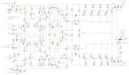
The high end improvement is very significant. I think it's due to the cascoded current source.
By the way, I chose that current source based on an earlier discussion here on DiyAudio. It's not the best for ripple rejection, but almost, and low parts count.
http://www.diyaudio.com/forums/solid-state/86626-searching-best-ccs.html
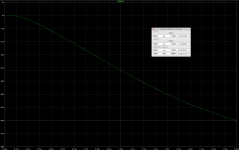
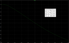
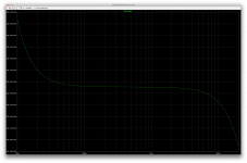
Below is the summary graphic.
Attachments
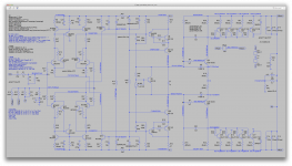
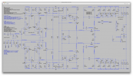
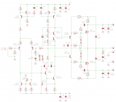
I reviewed the performance of our latest version, with zener CS, against an earlier version using mirror current sources. Actually, the mirror was better. So I refined it a bit to have a more constant current. This is an unconventional use of the mirror, but I'm keeping an open mind depending on performance.
Attachments
OK, so increasing to 470 is bad, try decreasing if not too much trouble. Go 47,22. I suspect it will do little.
Also, that 10k on the EF emitter must change for these changed values. It's important to scale that resistor. We need a ratio of between 50:1 and 100:1 between the mirror emitter resistors and that EF emitter resistor. In other words, we should have 5.6k to 100 ohm (10k is high), or 22k to 470 ohm, or say 2.2k to 47 if you go lower.
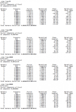
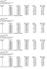
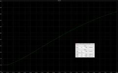
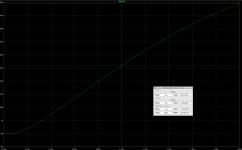
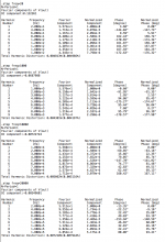
Ok, so to make things easier and have datasets with meaningful info for proper comparison, I'm putting values into variables to easily switch from one to the next and I will put out for each set of values the same info, thd, noise and slew rate.
Quite a bit of info, so I'm keeping it to what's most useful and I'll post each set separately.
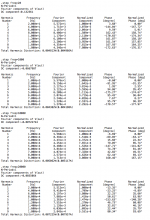
Starting with the mirror degen res at 22, and the EF emitter res 1k2 for that config.
With 22ohms, I tought the slew rate would be a little higher, but it's roughly the same. I take this as we have quite sufficient oomph in the ltp to drive the miller caps.
Noise goes up as expected, and thd is a little higher.
Using the recent results with 100ohms as being the reference.
I will re-post the data for 100ohms as well later on with the same info for best comparison.
So far, having seen 100, 470 (with the wrong EF res value) and now 22, I suspect we might be able to go a little above 100 to improve noise a little, if we don't go too far above that, so we stop before getting the diminishing return.
Seems like 100 might not be the optimal compromise, and perhaps we can edge towards 470 but without going too far.
Attachments
-
 Screen Shot 2016-12-22 at 3.45.17 PM.png179.8 KB · Views: 61
 -
 Screen Shot 2016-12-22 at 3.43.56 PM.png179.2 KB · Views: 65
 -
 Screen Shot 2016-12-22 at 3.41.53 PM.png243.7 KB · Views: 59
 -
 Screen Shot 2016-12-22 at 3.40.52 PM.png154 KB · Views: 62
 -
 Screen Shot 2016-12-22 at 3.40.37 PM.png760.7 KB · Views: 74
From 22 to 47, I can't say I see much difference.
Attachments
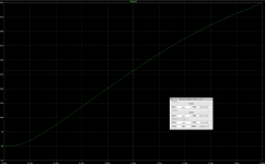
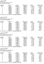
This serves as our reference for comparison. (100 & 10k. I left the 10k as we had before)
The slew rate hasn't been affected that much.
We should explore more values between 100 and 470. We may find a more optimal value that way. If slew rate remains roughly the same, we get lower noise and thd doesn't rise, we're in business.
The slew rate hasn't been affected that much.
We should explore more values between 100 and 470. We may find a more optimal value that way. If slew rate remains roughly the same, we get lower noise and thd doesn't rise, we're in business.
Attachments

Last edited:
I think it's something to keep going for, the slew rate remains good and we have better thd and noise. Not much, but improving, and the values haven't really changed much yet.
Attachments

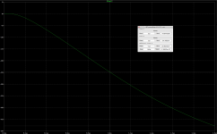
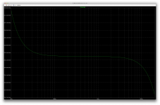
Here we're at 180 & 10k.
I was hoping to be able to continue gaining a little more with higher values, but it seems now although the noise gets a bit better, thd at hf starts getting worse.
(previous post was for 150 & 7k5)
I was hoping to be able to continue gaining a little more with higher values, but it seems now although the noise gets a bit better, thd at hf starts getting worse.
(previous post was for 150 & 7k5)
Attachments

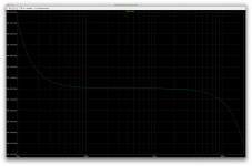
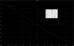
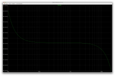
Here with 220 & 12k, the trend continues.
No need to bother looking at the slew rate, as it remains largely unaffected.
The noise continues dropping, and thd drops a little as well but not at hf, as it's rising instead.
So I consider this rather a diminishing return, if we gain a little with lower noise, lower thd at the lower frequencies is nice but at the highest end it's the opposite, so I don't see a good reason to try any higher values.
Unless we have something else along with it to try that would counteract on the hf thd rise...
The gain in lower noise is slim, and not really worth it, especially at the expense of hf thd rising.
Attachments

Here with 100 & 5k6 instead of 10k, to see what happens with a different ratio, as a comparison with our earlier reference.
No real change.
I guess going for 150 instead of 100 seems worth it, but higher probably not.
No real change.
I guess going for 150 instead of 100 seems worth it, but higher probably not.
Attachments
This serves as our reference for comparison.
...
We should explore more values between 100 and 470. We may find a more optimal value that way. If slew rate remains roughly the same, we get lower noise and thd doesn't rise, we're in business.
Certainly, my 100 ohm initial value was a swag based on the knee of the noise curve. Amazing the power of these simulations. Beware though, as the resistance rises, the VAS current will rise too. Results could be affected by VAS current changes, so we could be fooled. But this is a very worthwhile experiment.
For what it's worth, the venerable 741 op amp used 1k. It also used mirror current source for the LTP, I just noticed. Not such a new idea...
Attachments
Certainly, my 100 ohm initial value was a swag based on the knee of the noise curve. Amazing the power of these simulations. Beware though, as the resistance rises, the VAS current will rise too. Results could be affected by VAS current changes, so we could be fooled. But this is a very worthwhile experiment.
I have been keeping the bias in the outputs the same, but I haven't kept an eye on the vas bias.
Maybe it has something to do with that hf thd rising effect when going over 150ohms. If we could counteract this, it might be possible then to try a little higher without adverse effect.
With 180 the thd does get better except for the highest frequencies. That's a pitty.
For what it's worth, the venerable 741 op amp used 1k. It also used mirror current source for the LTP, I just noticed. Not such a new idea...
Very cool, we're not reinventing the wheel. Why not go with what works and is proven?
Makes me think there could be such ideas to draw from newer opamps...
I think it's something to keep going for, the slew rate remains good and we have better thd and noise. Not much, but improving, and the values haven't really changed much yet.
Whatever values you used in this one, best yet. 150/7.5k?
I'm wondering if the rising HF distortion has to do with value of the EF transistor's emitter resistor. That resistor is driving the bases and increasing it reduces HF drive in the mirror in one direction. Is it possible to vary this resistor to see if it is affecting distortion? Fix the other Rs, then vary this one. For instance, try no resistor, 100x, 50x, 25x, 10x, and only at 20kHz?
There is another design here with similar mirror. He's using 220/2k (10x). My impression is he did not do a lot of simulation, due to limited expertise with sim, but he proto'd it. Could be wrong. But the 10x ratio is interesting, and the 220.
Attachments
Last edited:
Whatever values you used in this one, best yet. 150/7.5k?
Yes. Best for thd, noise and didn't make slew rate any worse.
It's when going up to 180 that things get worse at hf only. Noise did lower and thd as well except at hf.
I'm wondering if the rising HF distortion has to do with value of the EF transistor's emitter resistor. That resistor is driving the bases and increasing it reduces HF drive in the mirror in one direction. Is it possible to vary this resistor to see if it is affecting distortion? Fix the other Rs, then vary this one. For instance, try no resistor, 100x, 50x, 25x, 10x, and only at 20kHz?
I'll try to whip something up. I'm working on your latest update for now.
Altering that res affects things a little, so I may have to do what I did earlier. Work out all the op points with each value, put them in variables and then run each sim.
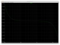
Varying just one value may allow easy plotting, which might be better than looking at raw numbers. A curve is better visually than numbers to immediately see a trend.
Should I try this out on the latest one in progress? Or just stay with the same one used for all those previous comparisons?
Spookydd said: Varying just one value may allow easy plotting, which might be better than looking at raw numbers. A curve is better visually than numbers to immediately see a trend.
Should I try this out on the latest one in progress? Or just stay with the same one used for all those previous comparisons?
I say: Stay with the one used before, I guess. Otherwise we'll be unable to directly compare with the results posted.
I think a plot is best too. Use your judgement. I generally look at the frequency and composite THD mostly, since I'm not sure what the harmonics mean. The gurus seem to know that for example a particular stage kicks out only odd harmonics or only even, by experience or analysis, which would be good to know.
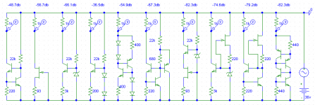
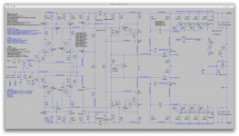
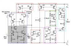
I'm curious if the latest version with the mirror CS has value. I admit I am skeptical, but very curious. It's an odd use for mirrors, no? But as I just realized they are workhorses in Op Amps. That 741 used 3 types of mirror, the EF, basic, and Widlar. Just for laughs here is a classic audio amp (HK Citation 16) that uses 3 Wilson mirrors cleverly in the front end; I think the designer was an IC designer first.
Should I try this out on the latest one in progress? Or just stay with the same one used for all those previous comparisons?
I say: Stay with the one used before, I guess. Otherwise we'll be unable to directly compare with the results posted.
I think a plot is best too. Use your judgement. I generally look at the frequency and composite THD mostly, since I'm not sure what the harmonics mean. The gurus seem to know that for example a particular stage kicks out only odd harmonics or only even, by experience or analysis, which would be good to know.
I'm curious if the latest version with the mirror CS has value. I admit I am skeptical, but very curious. It's an odd use for mirrors, no? But as I just realized they are workhorses in Op Amps. That 741 used 3 types of mirror, the EF, basic, and Widlar. Just for laughs here is a classic audio amp (HK Citation 16) that uses 3 Wilson mirrors cleverly in the front end; I think the designer was an IC designer first.
Attachments
I say: Stay with the one used before, I guess. Otherwise we'll be unable to directly compare with the results posted.
Ok, I'll get back to it when I'm done with the last updates.
I generally look at the frequency and composite THD mostly, since I'm not sure what the harmonics mean. The gurus seem to know that for example a particular stage kicks out only odd harmonics or only even, by experience or analysis, which would be good to know.
You haven't looked at enough FFT plots yet. We'll do some of that once we finalize the schematic and start looking a little deeper at the details. With higher resolution on FFT plots, the harmonics should start speaking to you...
I'm curious if the latest version with the mirror CS has value. I admit I am skeptical, but very curious.
You'll know very shortly. Working on it right now.
It's an odd use for mirrors, no? But as I just realized they are workhorses in Op Amps.
Whatever works. And in opamps they tend to use things we don't or rarely use.
- Status
- Not open for further replies.
- Home
- Amplifiers
- Solid State
- grounded collector amp