For one thing, the base stoppers on the mirrors didn't seem to add anything before, and now removed, although there are 2 more devices there, it doesn't seem to make any difference either.
So I suspect we can forgo using base stoppers on the mirrors. Although they did look like they generated noise, they didn't really influence much the total noise figure. So whatever noise they caused locally, didn't seem to affect things globally very much.
So I suspect we can forgo using base stoppers on the mirrors. Although they did look like they generated noise, they didn't really influence much the total noise figure. So whatever noise they caused locally, didn't seem to affect things globally very much.
I'm curious to know what would an enhanced wilson mirror bring, and what drawbacks as well.
Self shows how much the improved mirrors affect performances, and it looks like simply stacking 2 mirrors on top of each other as an enhanced wilson mirror would be beneficial, although more complex with a higher part count.
I wonder how noise would be affected globally that way too.
It would certainly change the operating point and biasing. And some values would require adjustments.
Attachments

I'm trying to understand how the gain is worked out in this configuration.
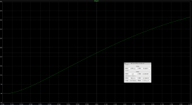
We do have the input filter that removes a little bit of input signal, not much, as we have 1.35V peak at the input, which is about 954mV rms, and we end up with about 891mV rms after that filter, but then the closed loop's gain should be determined only by the global feedback res at 20k and the return to ground through the caps at 330, which is a ratio of 60.6, but actual figures of gain are a little over 41 with the input filter taken into account, and about 44 and change if we take out the input filter effect.
Then the measurements show that we have an output voltage at about 39.395V rms, with the input rms at 954mV, we have an actual ratio of about 41.29.
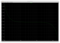
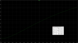
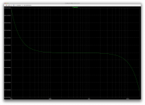
20 log of that gives almost 32.32db, which is also shown on the ac analysis in the pass band's flat area.
So we do have a closed loop's actual real gain of a little more than 41 (32.32db), but the ratio of the 20k and 330 feedback res aren't in that ratio.
So I'm missing something here. The difference between the calculated ratio of about 60.6 and the actual of a bit more than 41 doesn't jive. What a I missing?
The weirdest part is what's reported by the tian probe, about the open loop gain being less than the closed loop one, at somewhere near 10db only of open loop gain. We also have that huge gain spike in hf in the open loop gain curve, which I find quite puzzling too.
If we are to have a closed loop gain at some 32db and change, logically the open loop gain should be more than that, even if modest, it should be quite a bit more, and then closing the loop would have an effect on thd and other things.
Most amps have some 100-120db of open loop gain, but we don't even really need that much, but logically we do need more than 10db.
We do have the input filter that removes a little bit of input signal, not much, as we have 1.35V peak at the input, which is about 954mV rms, and we end up with about 891mV rms after that filter, but then the closed loop's gain should be determined only by the global feedback res at 20k and the return to ground through the caps at 330, which is a ratio of 60.6, but actual figures of gain are a little over 41 with the input filter taken into account, and about 44 and change if we take out the input filter effect.
Then the measurements show that we have an output voltage at about 39.395V rms, with the input rms at 954mV, we have an actual ratio of about 41.29.
20 log of that gives almost 32.32db, which is also shown on the ac analysis in the pass band's flat area.
So we do have a closed loop's actual real gain of a little more than 41 (32.32db), but the ratio of the 20k and 330 feedback res aren't in that ratio.
So I'm missing something here. The difference between the calculated ratio of about 60.6 and the actual of a bit more than 41 doesn't jive. What a I missing?
The weirdest part is what's reported by the tian probe, about the open loop gain being less than the closed loop one, at somewhere near 10db only of open loop gain. We also have that huge gain spike in hf in the open loop gain curve, which I find quite puzzling too.
If we are to have a closed loop gain at some 32db and change, logically the open loop gain should be more than that, even if modest, it should be quite a bit more, and then closing the loop would have an effect on thd and other things.
Most amps have some 100-120db of open loop gain, but we don't even really need that much, but logically we do need more than 10db.
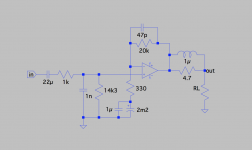
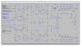
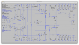
To simplify the reasoning on this gain issue, I drew up a very simplified schematic of the amp, keeping only it's input and output filters and the feedback network, to make it look like an opamp.
This being an non inverting amp, we should have the closed loop gain ratio (ignoring the input filter) of 1 + ( 20k / 330 ) = 61.6
Am I wrong here somewhere?
That is much more than the actual 41 something that is actually found.
Is this because we don't have enough open loop gain and the amp isn't actually able to provide all the gain the closed loop is set for? Or is there something else I'm not understanding?
Attachments
To simplify the reasoning on this gain issue,... make it look like an opamp.
we should have the closed loop gain ratio (ignoring the input filter) of 1 + ( 20k / 330 ) = 61.6
...
That is much more than the actual 41 something that is actually found.
Is this because we don't have enough open loop gain and the amp isn't actually able to provide all the gain the closed loop is set for? Or is there something else I'm not understanding?
Ahh, no mystery. It's all good.
You are neglecting the contribution of the two 100k resistors in parallel with the 20k. These 3 resistors are effectively in parallel for AC, and our circuit demands that the DC components from the 100k resistors cancel, so they truly are in parallel. The input resistance is the Thevenin equivalent of these three resistors. Using the formula for parallel resistance, the effective resistance is 1.4286e+4, or about 14.3k (to pick the closest 1% value), which is the exact resistance we use on the non-inverting input to ground, to balance input currents. That results in a computed closed loop gain of 44.3, and the actual gain of 41 is close to predicted value, though I don't know exactly where the 8% error comes in.
Don't worry about open loop gain, by the way. We have a lot. The front end alone has a gain over 1 million. The VAS has a further gain of about 8, constrained by the 180k/22k network. The next major step will be to unconstrain the VAS, but first I have some other minor changes to check out. One way to observe the front end gain would be to remove the global feedback and the connection to the output stage and drive it as an independent amp. It has way too much gain to work as anything but a comparator though. You could put in a dummy feedback network of say 1M/1k around the front end to assure yourself that the front end has ample open loop gain.
I am desolate. The enhanced current mirror did almost nothing for distortion/noise. The cascoded current source did almost nothing too. Of course we would not know if we did not try them. I suppose a negative result is success too. So, what next?
I will leave our two latest mods in for now, but they probably go away soon.
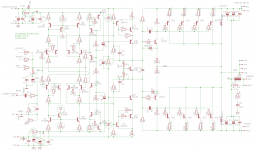
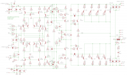
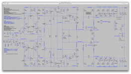
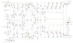
I am posting below our current circuit, with minor changes. We have enhanced the power filter for the front end, reduced the constant current by half to minimize voltage loss in said power filter, changed the enhanced mirror slightly and simplified the VAS cascode slightly. These should have almost no effect, except for reduction in VAS current. OH, and hopefully reduced low frequency coupling from the VAS to the differential pair. I'm really trying to reduce the low frequency noise mainly.
Attachments
You are neglecting the contribution of the two 100k resistors in parallel with the 20k. These 3 resistors are effectively in parallel for AC, and our circuit demands that the DC components from the 100k resistors cancel, so they truly are in parallel. The input resistance is the Thevenin equivalent of these three resistors. Using the formula for parallel resistance, the effective resistance is 1.4286e+4, or about 14.3k (to pick the closest 1% value), which is the exact resistance we use on the non-inverting input to ground, to balance input currents. That results in a computed closed loop gain of 44.3, and the actual gain of 41 is close to predicted value, though I don't know exactly where the 8% error comes in.
Man! That's what I was missing.
I was only looking at that divider as the generator of the virtual middle point between the rails, not thinking it was playing any role in the gain.
This is great! This is how we learn things, and the sharing...
Don't worry about open loop gain, by the way. We have a lot. The front end alone has a gain over 1 million.
I knew that ltp stage would be such a high gain one, and the main supplier for the open loop gain, but aren't we limiting it somewhat with local feedback?
The VAS has a further gain of about 8, constrained by the 180k/22k network.
I was really wondering about that. Coupled with the output stage's gain, that may not be huge, but it's not near nothing.
The next major step will be to unconstrain the VAS,
How much gain would get loose if that vas wasn't locally fed back?
One way to observe the front end gain would be to remove the global feedback and the connection to the output stage and drive it as an independent amp.
We've sort of done something like that early in this quest, but with the earlier version when we didn't use the centering divider.
And I actually did test this, in a way, by disconnecting the global feedback from the in-, several post ago, when I was trying to figure out why the tian probe appeared to be either lying to me or perhaps something was wrong in the circuit that was the cause.
And now having in mind the fact that the 100k divider res are actually a part of what determines closed loop gain, I am thinking this could be why the tian probe is giving those inconsistent results.
When I inserted the tian probe, it was inside the return feedback from the output, which when stepping through its measurements, acts on the global feedback loop.
However, due to our "very special" topo, we still have those 100k res there, basically outside that global feedback loop, but affecting gain.
And that may be why the open loop reported is looking extremely feeble at some 10db. And it also has that nasty huge gain spike at hf.
At the moment I don't see how the tian probe can be made to work properly, since we can insert it in a way that does include those 100k res. And those res just cannot be taken out of the circuit without causing an imbalance.
It has way too much gain to work as anything but a comparator though.
Yes, it would be impossible to work properly open loop that way. Although when I tried cutting the global feedback, it did work fairly well as is, without that feedback, but the 100k divider res were still there though, and that changes things.
You could put in a dummy feedback network of say 1M/1k around the front end to assure yourself that the front end has ample open loop gain.
Well, we don't really need to verify that we have plenty of gain there. This type of stage is known to have plenty of it and in the majority of amps, it's almost the sole supplier of gain, and most amps have that open loop gain in the 100-120db range.
And if we do have some 1 million of gain right there in that ltp stage, then that's 120db already.
The cascoded current source did almost nothing too.
Actually I think that did reduce thd slightly, and made it lower where it was going up faster than it should, which is at the lowest end of the bandpass.
True, it didn't really change things, but we got a slightly better thd performance from it.
Of course we would not know if we did not try them. I suppose a negative result is success too. So, what next?
The beauty of simulating! We can do anything and not spend anything on parts, risk blowing stuff up, and waste time plugging, soldering and measuring.
I am posting below our current circuit, with minor changes. We have enhanced the power filter for the front end, reduced the constant current by half to minimize voltage loss in said power filter, changed the enhanced mirror slightly and simplified the VAS cascode slightly. These should have almost no effect, except for reduction in VAS current. OH, and hopefully reduced low frequency coupling from the VAS to the differential pair. I'm really trying to reduce the low frequency noise mainly.
As far as thd is concerned, it didn't change much.
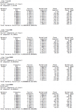
To make things easier, I made it step through the 20,1k,10k and 20k frequencies, to get those results in a single shot.
The thd is roughly the same as before.
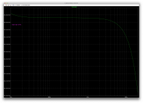
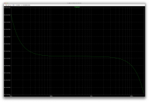
The noise is also roughly the same, perhaps a tiny bit higher and no change at the low end, with that rapid climb below about 50hz.
However, going on a hunch, I tried changing the 22u input cap to a 47u, and look at what happens!
The noise rapid climb start much lower and that does change things quite a bit.
So to minimize that climbing noise at the low end, I guess only that input cap needs a larger value...
Attachments

There is one more little experiment that I tried earlier, with our previous incarnation.
I tried stepping through several values for the big filter caps, to see what the effect is at the various frequencies.
I was curious to know how to determine the value for those big caps, and I wouldn't mind having an idea about what calculations involve.
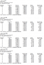
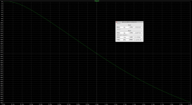
However, stepping through the values of 2200u, 2700u, 3300u, 3900u, 4700u, 5600u, 6800u and up to 10000u, for each stepped frequency value of 20,200,1k,5k,10k and 20k, I have found out something interesting, about thd.
This took quite some time to run, because of the large step count to go through, and the result is a little too large to post here.
But what I found out is that their value has basically no impact at all above about 1khz (on thd, don't know about noise for now). They do have a tiny, barely noticeable effect (higher thd) at 1khz, but negligible.
However, their value starts having some impact at 200hz, and it's most felt at the lowest frequency, with a serious effect at 20hz.
And furthermore, there is a "sweet spot" for their value, with too high or too low values increase thd rapidly, while the optimal value keeps thd at 20hz close to what it is at 1khz.
Having done that, I find that 4700u seems effectively a little higher than needed, for best thd at the low end.
This is totally counter to what I would've thought. I was thinking, the higher the better for best low end performance, but not so!
The best thd level at 20hz is with the 3900u, and it gets worse at 3300u or below, as well as 4700u and above.
Now I stepped through values that can be obtained, and didn't try spotting that exact sweet spot value. But this is rather edifying I think.
I tried stepping through several values for the big filter caps, to see what the effect is at the various frequencies.
I was curious to know how to determine the value for those big caps, and I wouldn't mind having an idea about what calculations involve.
However, stepping through the values of 2200u, 2700u, 3300u, 3900u, 4700u, 5600u, 6800u and up to 10000u, for each stepped frequency value of 20,200,1k,5k,10k and 20k, I have found out something interesting, about thd.
This took quite some time to run, because of the large step count to go through, and the result is a little too large to post here.
But what I found out is that their value has basically no impact at all above about 1khz (on thd, don't know about noise for now). They do have a tiny, barely noticeable effect (higher thd) at 1khz, but negligible.
However, their value starts having some impact at 200hz, and it's most felt at the lowest frequency, with a serious effect at 20hz.
And furthermore, there is a "sweet spot" for their value, with too high or too low values increase thd rapidly, while the optimal value keeps thd at 20hz close to what it is at 1khz.
Having done that, I find that 4700u seems effectively a little higher than needed, for best thd at the low end.
This is totally counter to what I would've thought. I was thinking, the higher the better for best low end performance, but not so!
The best thd level at 20hz is with the 3900u, and it gets worse at 3300u or below, as well as 4700u and above.
Now I stepped through values that can be obtained, and didn't try spotting that exact sweet spot value. But this is rather edifying I think.
OK, so with all the minor changes nothing broke, or even changed much. You identify the Input Cap as the source of the rising distortion, logical. And you identified a sensitivity to the power filter values that is not so logical, but there it is. Progress.
Regarding the Input cap, I increased the input cap from 10uf to 22uf when we reduced the input resistance from 33k to 14k, out of concern for input cap distortion. Actually, it's below audibility, but it's good to confirm the source.
As you know, the RC constant of the input cap and 14.3k input resistor determines that point of rising distortion. If the circuit will remain centered, we can increase the R and avoid larger input cap values. For example, double the NFB resistors and the input resistor, keeping the ratios the same. I don't want a large NP cap on the input if we can avoid it. See attached schematic, in which I also deleted the local NFB on the VAS as an experiment.
Regarding the front end power filter change, it apparently did little to reduce noise. I expected some improvement. It's a benign change, except we had to reduce tail current to minimize shifts in the operating point of the VAS.
By the way, with the reduced tail current, did we lose slew rate when we halved the tail current? I expect some reduction, just hope not a serious loss. For now I will leave it alone, unless we had a serious loss of slew rate.
Attachments
Last edited:
I'm wondering how dual current mirrors will work as current sources. Purely as a curiosity, can you simulate this idea?
Attachments
Last edited:
For evaluation: Wilson Current Mirror
Attachments

Last edited:
OK, so with all the minor changes nothing broke, or even changed much.
And we're zeroing in on some ghosts though.
Regarding the front end power filter change, it apparently did little to reduce noise. I expected some improvement. It's a benign change, except we had to reduce tail current to minimize shifts in the operating point of the VAS.
There is the possibility that something would be a little different in a real circuit.
Although I did add some series resistance to the 15V voltage supplies (quite a bit in fact), it's still fairly ideal.
By the way, with the reduced tail current, did we lose slew rate when we halved the tail current? I expect some reduction, just hope not a serious loss. For now I will leave it alone, unless we had a serious loss of slew rate.
Ok, before trying your latest changes from this post, I looked at the slew rate as it stands now on the previous last update.
I think it's quite decent, and rather even between the neg and pos sides.
We have a little over 23V on the rising edge and a little bit less on the falling one, but still about 23V. Not bad really. Not super fast, but definitely high end hifi.
We have fairly small values for the miller caps, so we're not lacking a lot of oomph in the ltp to charge them.
I'll work on the latest changes later one today.
Attachments

As you know, the RC constant of the input cap and 14.3k input resistor determines that point of rising distortion. If the circuit will remain centered, we can increase the R and avoid larger input cap values. For example, double the NFB resistors and the input resistor, keeping the ratios the same. I don't want a large NP cap on the input if we can avoid it. See attached schematic, in which I also deleted the local NFB on the VAS as an experiment.
With those changes, the vas bias has dropped a lot and the centering although still quite good, has close to 9mV of offset, as opposed to the lower than 1mV previously. But that's not the main concern, we're still less than 10mV away from perfect balance.
The change of the feedback scheme also changes the compensation, so we have oscillations reappearing, which demands adjustments on the compensation.
Once the comp cap values drop, the oscillations do stop, but thd has blown way up.
Adjusting down further the comp cap values lowers thd some more, but I have no idea what the phase/gain margin are, since I can't get the tian probe to look at it.
I'm not even looking at noise right now, as the thd is so much higher, this doesn't seem the right way to go at all.
We've been mostly below 50ppm of thd across most of the passband and now we're more around 0.1% and even close to 0.2% at the low end. Not really good, and definitely nowhere as good as what we've had lately.
I've been trying to figure out what to do to get the tian probe working right, but haven't found any way to get this to work right. We just can't disconnect the centering res and we can't properly get the open loop working without them.
Right now I don't see how we can look at the open loop.
Attachments
I'm wondering how dual current mirrors will work as current sources. Purely as a curiosity, can you simulate this idea?
Looks like we need to reverse some of the changes before trying this out. At least we need to get the feedback to work better as before, or this simulation won't provide anything really useful.
For evaluation: Wilson Current Mirror
That too would be better tried with a better working circuit as earlier.
The high thd is a step backwards right now. Don't know about noise...
I'm wondering how dual current mirrors will work as current sources. Purely as a curiosity, can you simulate this idea?
This seems to me to be a good way to go.
Lower part count and a little improvement.
A tiny bit lower noise.
The slew rate about the same but perhaps a tiny bit closer to each other for both sides, despite a slightly lower tail current.
No need to alter the compensation.
The thd isn't bad, and I haven't touched the feedback res.
Attachments
-
 Screen Shot 2016-12-21 at 2.30.09 PM.png689.5 KB · Views: 62
 -
 Screen Shot 2016-12-21 at 2.29.34 PM.png181.7 KB · Views: 62
 -
 Screen Shot 2016-12-21 at 2.31.00 PM.png257.6 KB · Views: 61
 -
 Screen Shot 2016-12-21 at 2.33.15 PM.png187.7 KB · Views: 65
 -
 Screen Shot 2016-12-21 at 2.35.17 PM.png233.8 KB · Views: 55
For evaluation: Wilson Current Mirror
Since the previous attempt at modifying the global feedback and centering res had such a bad effect on thd, I tried this on our previous version that works well, with the change of the CS for the CM, and tried with the vas feedback removed.
It's not biasing.
I tried then to reconnect the vas feedback, and tried 22k, 33k and 47k for the vas other base res and it won't bias with any of that.
The ltp remains totally imbalanced.
I guess the wilson requires a little more headroom.
Attachments


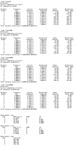
I tried one more small experiment to see if it would reduce the noise.
As Self describes in his book, it is possible to parallel transistors to reduce their effect on noise. With 2 in parallel, the noise is supposed to be cut in half (-3db), so I figured I'd try that just to see what happens, on the biggest noise contributors, the ltp's mirrors.
The result isn't what I would expect, which is very little effect.
And that makes me wonder, with the mirrors being such a noise source, their contribution to the total noise should be more significant, so halving their noise contribution should logically have a much bigger effect, but that's not the case.
So now I'm thinking although the mirrors seem to be a sizable noise source, perhaps not that much of that is actually passed on the whole circuit.
Perhaps the ones that would get more of an effect would be the actual ltp, but since we have the sziklai there, it gets rather complex to try that, the part count climbs quick.
I tested one thing earlier, in our most successful version of late, which is to remove the sziklai pairs to see what they are bringing.
And once removed, the thd pretty much doubled. So they are good to have there.
OK, reset back to an earlier version that worked better, say from post 385, version 13.0.08
Scaling up the feedback resistors is a fail. Removing the 180k on the VAS is a fail. We should step back to stability.
What did we learn?
The feedback resistors are about right.
We really do need the local NFB on the VAS. It probably compensates for the fact that the complementary transistors in upper and lower halves are not identical, forcing them to behave more alike and definitely improving centering. We can't lose grip on that.
What about those various other mods, the EF current mirror, Wilson CM, and mirrored current source?
Wilson mirror is not better in this circuit because it apparently needs more headroom, which does not match the needs of the next stage, the VAS. Since the EF mirror is about as good and matches much better, I prefer it. But we learned something about Wilson mirrors.
As for the mods in this version 13.0.08 (the enhanced current mirror and cascoded current source), those mods at least do no harm, and at best make a slight performance improvement.
About the dual mirror current source: It's simple, but it's not a regulated current source, just a current mirror. The current is set solely by the input current through one resistor, which I find elegant. But any noise on that input current passes directly to the tails, so a filter must be added on the input current. At that point, it is nearly identical in complexity to the separate current sources we had before. I'm not sold on it. Based on other discussions on DiyAudio, I will mod the CS.
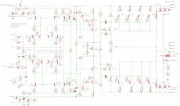
I'm posting below the earlier version 13.0.8, and a new version with simplified current sources .
Scaling up the feedback resistors is a fail. Removing the 180k on the VAS is a fail. We should step back to stability.
What did we learn?
The feedback resistors are about right.
We really do need the local NFB on the VAS. It probably compensates for the fact that the complementary transistors in upper and lower halves are not identical, forcing them to behave more alike and definitely improving centering. We can't lose grip on that.
What about those various other mods, the EF current mirror, Wilson CM, and mirrored current source?
Wilson mirror is not better in this circuit because it apparently needs more headroom, which does not match the needs of the next stage, the VAS. Since the EF mirror is about as good and matches much better, I prefer it. But we learned something about Wilson mirrors.
As for the mods in this version 13.0.08 (the enhanced current mirror and cascoded current source), those mods at least do no harm, and at best make a slight performance improvement.
About the dual mirror current source: It's simple, but it's not a regulated current source, just a current mirror. The current is set solely by the input current through one resistor, which I find elegant. But any noise on that input current passes directly to the tails, so a filter must be added on the input current. At that point, it is nearly identical in complexity to the separate current sources we had before. I'm not sold on it. Based on other discussions on DiyAudio, I will mod the CS.
I'm posting below the earlier version 13.0.8, and a new version with simplified current sources .
Attachments

Last edited:
Spookydd said: I tested one thing earlier, in our most successful version of late, which is to remove the sziklai pairs to see what they are bringing.
And once removed, the thd pretty much doubled. So they are good to have there.
I say: Yes, exactly as expected. Self says that they should do better than that in theory by about 5x, but in actual practice Szlikai pairs only halve distortion. They do another good thing too, reduce input current, which in effect reduces offset.
Regarding CM noise, increasing the emitter resistors reduces it. I picked 100 ohm, but higher values give lower noise. Side effect, the DC level to the VAS increases, so we'd have to watch that. Try 470 ohm? Just a thought.
OK, reset back to an earlier version that worked better, say from post 385, version 13.0.08
Yes, this is the one I've been using as a reference as being our most successful so far. And the few experiments I tried were done on that.
As for the mods in this version 13.0.08 (the enhanced current mirror and cascoded current source), those mods at least do no harm, and at best make a slight performance improvement.
Yes, switching the source to the mirror for the ltp tails did slightly improve thd, but nothing much for noise, just a little.
About the dual mirror current source: It's simple, but it's not a regulated current source, just a current mirror. The current is set solely by the input current through one resistor, which I find elegant.
What could the drawbacks be?
It did improve noise, but only slightly, and thd as well, very little, but a bit.
I'm posting below the earlier version 13.0.8, and a new version with simplified current sources.
This has slightly increased the noise. We had slightly less than 244 earlier and now it's almost 244.4. Really tiny difference though, although in the wrong direction.
The thd is basically the same except at 20k where we have a slight increase.
So that too isn't really in the right direction. (compare with my post at #386)
Attachments

- Status
- Not open for further replies.
- Home
- Amplifiers
- Solid State
- grounded collector amp