All the To220, To247, To264 BJT have the same BCE pin out.
All the To126 BJT have the same reversed ECB pin out.
Most of the 2sa/c To92 and BC..L have the same BCE pin out as the To220
Most BC & Eline have the pin out CBE.
2N & MPSA are reversed to EBC
All the To126 BJT have the same reversed ECB pin out.
Most of the 2sa/c To92 and BC..L have the same BCE pin out as the To220
Most BC & Eline have the pin out CBE.
2N & MPSA are reversed to EBC
All the To220, To247, To264 BJT have the same BCE pin out.
All the To126 BJT have the same reversed ECB pin out.
Most of the 2sa/c To92 and BC..L have the same BCE pin out as the To220
Most BC & Eline have the pin out CBE.
2N & MPSA are reversed to EBC
Thanks, its understood. without reading the datasheet, i would not think of populating especially when replacements are concerned.
i still like to know whether i can use
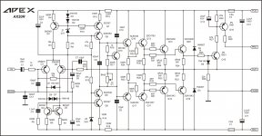
1. Q1/Q3 2N5551
2. Q5/Q6 2N5401/2N551 with resistor R12/R16 increased.
3. Q8 and Q9- MJE 15030/31 with small to-220 PCB mount heat sink
Hi Bimo,
Also 1381/3503 and 4793/1837 are not available with me right now. I do have many MJE15032/33 for Q8 and Q9. can I use those?
Prasi
You can use MJE15032/33.
For VAS transistor you can use higher power dissipation than 2N5401/2N5551 but with same or lower Cob. Higher Cob may be need to adjust capacitor compensation's value.
nice! why "R" ?
Because all letters from A to R had been already used. 😛😉😀🙂
Attachments
You can use MJE15032/33.
For VAS transistor you can use higher power dissipation than 2N5401/2N5551 but with same or lower Cob. Higher Cob may be need to adjust capacitor compensation's value.
Thank you Bimo,
I will order what I do not have (KSA1381, KSC3503) and then start building.
One more thing, is there any particular reason why you have used 1/2 W resistors in places of R20/21, R19, R17/18, R9 ?
I looked at the sim, the dissipation is quite less in those resistors, to minimize temperature effect?
reg
Prasi
I would always try to achieve a target dissipation of less than 50% of the resistor max rating.
In sensitive areas, like the NFB loop I aim for much less, usually <10% of max rating.
And also try to avoid excessive voltage effects: two 10k in series is better than two 40k in parallel.
In sensitive areas, like the NFB loop I aim for much less, usually <10% of max rating.
And also try to avoid excessive voltage effects: two 10k in series is better than two 40k in parallel.
I would always try to achieve a target dissipation of less than 50% of the resistor max rating.
In sensitive areas, like the NFB loop I aim for much less, usually <10% of max rating.
And also try to avoid excessive voltage effects: two 10k in series is better than two 40k in parallel.
In that case I think 1/4 w will be more than sufficient, as max dissipation in R19 is abt 8mW. R17/18 about 6mW. rest of the resistors have dissipation in uW's range. Unless ofcourse I am reading wrongly in the LTSpice.
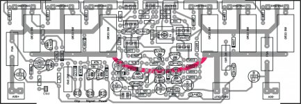
Hi sir Apex i want to make this amp , so is this the corect pcb? what can replace the bd679? which is the power of the amplifier on 8R and 4R? Thanks and sorry for my english.
An externally hosted image should be here but it was not working when we last tested it.
Hi sir Apex i want to make this amp , so is this the corect pcb? what can replace the bd679? which is the power of the amplifier on 8R and 4R? Thanks and sorry for my english.
An externally hosted image should be here but it was not working when we last tested it.
This pcb are ok...my ax-11 was made with this pcb.
An externally hosted image should be here but it was not working when we last tested it.
Hello...anyone can help me about AX20 with 3 pairs?...is possible use with +/-65V???
I think is yes possible
I think is not the same pcb! You modified the pcb?
Small modifications... just to put the big input capacitor and those of 100uF/100nF in supply rails.
Last edited:
- Home
- Amplifiers
- Solid State
- 100W Ultimate Fidelity Amplifier