Substitutes for 2SC4793 and 2SA1837
Hey Friends Happy DIY work, currently i am building APEX A40 and stuck with some fake Transiters which i got from local store. So i am ordering some genuine ones form element14.com here i got almost all ones beside the 2SC4793 and 2SA1837 pair they don't have it so is there any good substitutes for them.
Here are some pictures i like to share, Thank you...
[image]Image:APEX A40|thumb|none[/image]
[image]Image:APEX A40 1|thumb|none[/image]
[image]Image:APEX A40 2|thumb|none[/image]
[image]Image:APEX A40 3|none[/image]
Very nice.
You can use MJE15032/33.
This description is all wrong.Hey AndrewT, thanks for your help!
Transformer screen is connected to mains earth and chassis. At the moment it's isolated from transformers secondary DC ground. Amplifier inputs and outputs are also isolated from chassis/earth. The ground speaker return is directly connected to the star ground between the dc supply capacitors. At the amplifier PCB only one ground connection is used (also connected to star ground).
The mains PE direct to Chassis.
The transformer screen direct to Chassis.
The Speaker Return goes direct to the amplifier alongside or twisted with the Speaker Signal Hot, not to the chassis and not to the PSU.
If the PCB has one ground connection, then you need to check what connects to that pad. Signal Return, Speaker Return, supply rail decoupling?
And often a few others.
The transformer location is OK.Here is an image from amplifier build. PCB in the center is auxiliary psu/softstart and on the right side is the main psu+dc speaker protect. Do you think the transformer might be too near to amplifier pcb's?
The single wires criss-crossing all over the place are not OK.
Is it an Apex pcb?yeah.. second ax17 stereo module done..
I'm also building 2x PSU protect for a 4 channel amp with these boards. Had some trouble finding some relays that can safely break the output at high dc current. Watch out, most cheap relays are rated only for ac operation and will arc over the contacts when breaking large dc currents/voltages.
i think i'll be running each channel at 100W @8ohm at the most. I just needed some headroom since the output transistors are fairly cheap, so i've used 4 pairs for each channel 😛
An externally hosted image should be here but it was not working when we last tested it.
Where you find this?
This description is all wrong.
The mains PE direct to Chassis.
The transformer screen direct to Chassis.
The Speaker Return goes direct to the amplifier alongside or twisted with the Speaker Signal Hot, not to the chassis and not to the PSU.
If the PCB has one ground connection, then you need to check what connects to that pad. Signal Return, Speaker Return, supply rail decoupling?
And often a few others.
Sorry, I think we misunderstood.
Mains PE and Transformer are connected as you wrote. The speaker ground return path might be a point. I'll check that first. The input signal wires are acutally rg178 coax cables using on board smb connectors. So they have their own ground pad on the amplifier PCB. Is there any point to twist DC supply rail connections?
regards
do you have any DC supply rails anywhere in your wiring/traces?Is there any point to twist DC supply rail connections?
The supplies to the PSU and to the amplifiers are pulsing currents, they are not constant DC.
Constant DC does not emit emi.
Varying DC current does emit emi.
And fast changing current emits a lot of HF emi.
do you have any DC supply rails anywhere in your wiring/traces?
The supplies to the PSU and to the amplifiers are pulsing currents, they are not constant DC.
Constant DC does not emit emi.
Varying DC current does emit emi.
And fast changing current emits a lot of HF emi.
The PSU+Protect circuit does extract some DC from the +55V rail for speaker relay and monitoring. But the hum noise is also there without any relay. In addition to the main filtering capacitors each amp pcb has 2x2.300µF. With a speaker load of 4 Ohm they give a cutoff frequency of about 17Hz. Do you think that EMI might still be a Problem at such low Frequencies?
I doubt that.The PSU+Protect circuit does extract some DC from the +55V rail for speaker relay and monitoring.
Yes.But the hum noise is also there without any relay. In addition to the main filtering capacitors each amp pcb has 2x2.300µF. With a speaker load of 4 Ohm they give a cutoff frequency of about 17Hz. Do you think that EMI might still be a Problem at such low Frequencies?
which image showsyou can clearly see that in the attached image in post #6091
The PSU+Protect circuit does extract some DC from the +55V
I am not at my computer but if you look back in this thread, I posted the pdfs for the TB3. It includes a couple jumpers on the balance pot that I found to be necessary for proper function.
Hi Mr.Terry,
Thanks.It was your TB3 iron transfer pdf, that i downloaded.I will post a pic after completing the build.
Hello Sir Apex, I am going to do the TB3 build just curious about the frequency response of the ckt in lows and highs. So can you please tell me that thanku.
Hello Mr.Mile,
I am in the process of building your TB3.Ijust wanted to know can i power it up with your +/- 12 volt shunt supply( the one that you have designed with 2n5551 and 2n5401.
I also convey thanks for your TWO BAND tone control based on TLO74.Its the best one so far.All other schematics provided an unnatural midrange boost.But your circuit has the most neutral, sweet sounding tone.Eager to build TB3 also.I will post updates.
Thanks Mr.Terry, for your TB3 layout pdf.
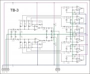
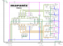
TB3 schematic with add jumpers on balance pot.
nice sch, but doesnt have the typical APEX looks to it.

Hello Sir Apex, I am going to do the TB3 build just curious about the frequency response of the ckt in lows and highs. So can you please tell me that thanku.
TB3 use graphic equaliser circuit, you can change frequency response if you want.
Regards
Hello Mr.Mile,
I am in the process of building your TB3.Ijust wanted to know can i power it up with your +/- 12 volt shunt supply( the one that you have designed with 2n5551 and 2n5401.
I also convey thanks for your TWO BAND tone control based on TLO74.Its the best one so far.All other schematics provided an unnatural midrange boost.But your circuit has the most neutral, sweet sounding tone.Eager to build TB3 also.I will post updates.
Thanks Mr.Terry, for your TB3 layout pdf.
Yes you can use +/-12V shunt supply or any regulated psu from +/-9V to +/-18V.
Regards
nice sch, but doesnt have the typical APEX looks to it.
It have marantz look, basicly it is qraphic equaliser.
- Home
- Amplifiers
- Solid State
- 100W Ultimate Fidelity Amplifier