this is what happnes for me under linux:
(this is 24 bit put in 32)
Code:
sox -b 32 -t alsa hw:0,0 -r 96000 -t alsa hw:0,0 -V --buffer 65536 biquad 0.25 -0.213383075 -0.027615075 1.0 -1.866634 0.8670602

sox:      SoX v14.4.2

Input File     : 'hw:0,0' (alsa)
Channels       : 2
Sample Rate    : 96000
Precision      : 32-bit
Sample Encoding: 32-bit Signed Integer PCM
Endian Type    : little
Reverse Nibbles: no
Reverse Bits   : no


Output File    : 'hw:0,0' (alsa)
Channels       : 2
Sample Rate    : 96000
Precision      : 32-bit
Sample Encoding: 32-bit Signed Integer PCM
Endian Type    : little
Reverse Nibbles: no
Reverse Bits   : no

sox INFO sox: effects chain: input        96000Hz  2 channels
sox INFO sox: effects chain: biquad       96000Hz  2 channels
sox INFO sox: effects chain: output       96000Hz  2 channels
(this is 24 bit put in 32)
I was doing some research this evening into the various ideas on cartridge loading for MM and how to get a flat response (coming across this long, but interesting thread from 2011 Near-zero capacitance effect for phono cables - method - Vinyl Engine . Note I think LuckyDog missed the input stage capacitance in his calculations) and realised that we have a big problem for those of use below a certain age, which is a lack of test disks we can trust. Will start another thread on that.
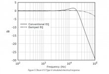
But back on track. Attached is a diagram from Bob Cordell's vinylTrak article (with thanks to Jan for letting me reproduce here). This shows the difference in (equalised) response between std cartridge loading and damped loading where you put a zero in the response at 8KHz and load the cartridge down to give HF roll off. It removes the peak, but also removes a potentially beneficial ultrasonic roll off. I say potentially as any ADC will have a front end filter anyway and I haven't yet done any sums to see what delta there is in HF energy. Looking at the resonant hump, although unwanted it doesn't look to hard to eq out anyway once you have biquads to spare and most of us can't hear that high anyway any more 🙂.
But back on track. Attached is a diagram from Bob Cordell's vinylTrak article (with thanks to Jan for letting me reproduce here). This shows the difference in (equalised) response between std cartridge loading and damped loading where you put a zero in the response at 8KHz and load the cartridge down to give HF roll off. It removes the peak, but also removes a potentially beneficial ultrasonic roll off. I say potentially as any ADC will have a front end filter anyway and I haven't yet done any sums to see what delta there is in HF energy. Looking at the resonant hump, although unwanted it doesn't look to hard to eq out anyway once you have biquads to spare and most of us can't hear that high anyway any more 🙂.
Attachments
I'll look more tonight but with multiple devices and even very close clocks there can be spectral leakage when doing the un-windowed FFT's
Scott, what you say sounds logical.
The ‘card loopback’ case involves one D-A, one A-D conversion and one clock.
The ‘card-MiniDSP –card’ case involves two D-A, two A-D conversions and two clocks.
The ‘TT cartridge-MiniDSP’ will involve one A-D, one D-A conversion and one clock.
But comparatively, window function will not change the cause of the leakage (new frequencies generated) which is the overloading.
As you have noticed, once the level of the peaks go down below approx –35dB, noise spectrum leakage reduces dramatically.
With a single test frequency, the soundcard starts distorting at a level of approx –1 to –2dB.
With 30 test frequencies it is to be expected that distortion will commence at much lower level. This level also depends on the frequencies phases relative to each other.
George
Attachments
One point of multi-tone is to get a more realistic crest factor. Before you put this test to bed, I did put a multi-tone up with RIAA pre-emphasis so the bass is at -20dB re: 1kHz. Maybe a more fair test for possible numerical overflow.
One last point, the miniDSP as some have found is on the edge in some applications and the gain structure of the whole signal path must be looked at carefully.
You are right if the bins with actual signal still look almost perfectly centered the empty bins should be from IMD/clipping mainly. I could run some numerical sims at 64bits to quantify this issue.
Last edited:
Scott, what you say sounds logical.
The ‘card loopback’ case involves one D-A, one A-D conversion and one clock.
The ‘card-MiniDSP –card’ case involves two D-A, two A-D conversions and two clocks.
The ‘TT cartridge-MiniDSP’ will involve one A-D, one D-A conversion and one clock.
But comparatively, window function will not change the cause of the leakage (new frequencies generated) which is the overloading.
As you have noticed, once the level of the peaks go down below approx –35dB, noise spectrum leakage reduces dramatically.
With a single test frequency, the soundcard starts distorting at a level of approx –1 to –2dB.
With 30 test frequencies it is to be expected that distortion will commence at much lower level. This level also depends on the frequencies phases relative to each other.
George
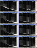
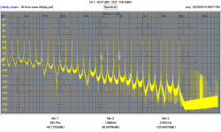
What resolution/windowing did you use? Here are some tests with that file.
Loopback EMU 1212M @192K 4M FFT
Allplay demo board (network player w/ Wolfson DAC) at 512K FFT
Allplay demo board (network player w/ Wolfson DAC) at 4M FFT
Praxis for FFT capture (and wave playback for loop test) Using Kaiser 7 term window.
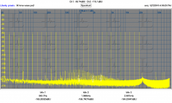
Several comments. First I'm not sure what the tone sequence is. It looks good for testing frequency response but I'm not sure that the IM and HD products are not on top of existing tones. You can see some IM products in the loopback test. For the Allplay demo board to ADC there are some harmonics and some IM products. No phono or speaker technology I know of could get near this resolution
Second, the 4M capture takes a long time and it seems there is enough drift between the two systems that while I get good results at 524K, 4M seems too long. The wraparound from end to beginning also causes a blip that affects the measurements quite a bit. I don't have the patience to make a 10 minute file out of the test tones so its speculation for now. I'm not sure how to find the right place to paste them together anyway.
What I don't see is massive breakdown in the DAC or ADC with so many tones. The output seems textbook perfect on analog loopback. I'm not sure of the playback levels in absolute terms, probably not at "bit perfect" levels in any case. That's for another day as well.
Attachments
this is what happnes for me under linux:
Code:sox -b 32 -t alsa hw:0,0 -r 96000 -t alsa hw:0,0 -V --buffer 65536 biquad 0.25 -0.213383075 -0.027615075 1.0 -1.866634 0.8670602 [/QUOTE] Thanks it turned out it was a Windows thing. I was under a mis-conception that it had to do with ASIO because of something the Audacity developers said. One of the SoX developers told me it simply is easier to do 16 bits because some devices don't support it and you have to negotiate the format 32 bit int, IEEE float normalized or non-normalized, or packed 24 bit. It was fun once getting 24 bit packed to work with endian flipping because bites are swapped on 16 bit boundaries. Both development groups think 24 bit recording only matters to pros. The new CoolEdit clone (thanks again Demian) ocenaudio works fine at 24 bits no need to try and turn on ASIO drivers. And yes alsa works too. I was also confused by the fact that under Win XP 2 drivers showed up in the CoolEdit device menu for my Maudio USB Duo and the little ASIO/Win dialog let me choose ASIO and I got 24 bits. I'm sure there are other things going on, Win audio is such a mess. I think that kickstarter thing is just a small Linux box, so really we are left with getting a good A/D for RPi.
Last edited:
Thanks it turned out it was a Windows thing. I was under a misconception that it had to do with ASIO because of something the Audacity developers said. One of the SoX developers told me it simply is easier to do 16 bits because some devices don't support it and you have to negotiate the format 32 bit int, IEEE float normalized or non-normalized, or packed 24 bit.
...
I think that kickstarter thing is just a small Linux box, so really we are left with getting a good A/D for RPi.
Good to know about SOX (thanks, Onvinyl!)
Does it make sense to do the first time constant in analog to improve SNR through the ADC? I know there is talk of it in this thread, but don't remember if anything definitive came of it.
Last edited:
At the moment, my workload is stiff. As soon as this situation relaxes, i'll try and change my first stage and feed sox with the updated biquad numbers.
Rüdiger
Rüdiger
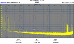
What resolution/windowing did you use? Here are some tests with that file.
65536 samples (0.732Hz resolution), no Window.
The test frequencies in that test file are selected for 48KHz sampling freq and 65536 FFT length.
Several comments. First I'm not sure what the tone sequence is. It looks good for testing frequency response but I'm not sure that the IM and HD products are not on top of existing tones.
Demian, this is Scott’s work and I am not to disclose the exact frequencies.
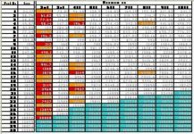
But I did investigate your question about the harmonics of the peaks (I checked up to the 10th harmonic).
On the attached blurred table:
With red are the harmonics that fall dead center in an FFT frequency bin.
With orange are the harmonics that fall on the skirts of an FFT frequency bin.
With marine blue are the harmonics that are above 24KHz so they fold back into the 0-24KHz spectrum but I haven’t yet calculated if they fall inside an FFT bin.
The problem is only with the 2nd and a bit with the 4th harmonics, which will not show up on the FFT.
So Scott, this set of frequencies is not good for testing single ended tube gear 😀
No phono or speaker technology I know of could get near this resolution
What I don't see is massive breakdown in the DAC or ADC with so many tones.
The output seems textbook perfect on analog loopback.
I agree.
That's for another day as well.
Yes. Me, I have to do the tests with the rest of Scott files.
George
Attachments
.
, so really we are left with getting a good A/D for RPi.
It smells like another famous diyaudio swarm project, mybe with this chip
Rüdiger
65536 samples (0.732Hz resolution), no Window.
The test frequencies in that test file are selected for 48KHz sampling freq and 65536 FFT length.
The frequencies are the closest multiples of 0.732Hz to the standard AES 1/3 octave center frequencies. 20-20k is about 10 octaves so 30 frequencies.
Last edited:
You mean we aren't going to do an all discrete multi-bit A to D with heroic de-glitcher?
And 20X the distortion of a $1 ADC?
What clock and sync signals come from the RPI? How clean are they? How high performance an ADC is needed /desired? Most of the ADC's I have looked at for audio are easily programmed by jumpers and don't need setup from the CPU to work. I would recommend the AK5394A since its one of the best, a mature available product and could be executed pretty easily. However if the clocks need help that needs to be addressed first. The board will cost more than the RPI (the chip above is over $20).
What clock and sync signals come from the RPI? How clean are they? How high performance an ADC is needed /desired? Most of the ADC's I have looked at for audio are easily programmed by jumpers and don't need setup from the CPU to work. I would recommend the AK5394A since its one of the best, a mature available product and could be executed pretty easily. However if the clocks need help that needs to be addressed first. The board will cost more than the RPI (the chip above is over $20).
And 20X the distortion of a $1 ADC?
What clock and sync signals come from the RPI? How clean are they? How high performance an ADC is needed /desired? Most of the ADC's I have looked at for audio are easily programmed by jumpers and don't need setup from the CPU to work. I would recommend the AK5394A since its one of the best, a mature available product and could be executed pretty easily. However if the clocks need help that needs to be addressed first. The board will cost more than the RPI (the chip above is over $20).
Seems I2S is recommended by some folks over USB. Unfortunately high quality output over input by far is where the work has been done. If you go to the HiFiBerry site you will see pictures of their products with the input circuitry all unpopulated but there connectors and all. This gets my hopes up. I don't think I have the skill to get a robust low level device driver to work.
https://audioberry.com/beginners-guide-raspberry-pi-i2s-audio/
This looks very interesting an I2S in and out FPGA, a possible repurpose? http://www.tjaekel.com/T-DAC/fpga.html
Last edited:
There is an AKM adc-chip that connects to i2s. Probably --this time - not discrete.
Rüdiger
Apparently there is a driver for I2S input at the processor level already written, I will keep searching. One expert pointed out that a user space I2S driver can't possibly work at 24/96. My sentiments exactly.
The question: Is anybody working on writing a sound driver for the hardware PCM module included in the Raspberry Pi? Or perhaps this driver is already there but nobody talks about it.
For those in the know it's trivial, but for the rest of us this subject is a great mystery.
I've got an I2S DAC built an tested with other platforms; it works fine at 44100 and 48000 frames per second, but I have no Idea what to do on the software side. An user space application doesn't do, my scope is to have good sound from the Pi without going through HDMI (of course no pwm either, thanks but no, thanks).
Last edited:
I expect it would be Alsa + a driver for the chips internal stuff. That must exist to be able to support any phone type application. Whether it supports 24/192 in is a separate question. it would be kernel space meaing access to the kernel source code is required if its not already done. USB is a lot of unnecessary overhead if you have a more direct path to the Alsa buffers.
Running the ADC in slave is the cleanest and getting a clean Master clock is essential for performance. Usually these guys run full duplex so the play and record clocks are the same as are the sample rates. That would make a board pretty simple to execute. Would it need both record and play? Still not hard. There are two efforts around DIYaudio for that exact combination. Getting one of them to share may be possible which would jumpstart this project.
Would the EQ code run in the DSP or as a userspace application?
You mean we aren't going to do an all discrete multi-bit A to D with heroic de-glitcher?
Next Linear Audio will have a tube DAC design. Not a DAC with a tube output stage (which is cheating of course) but a DAC with tubes as, ehh, DAC. 😎
From, who else, Marcel van de Gevel.
Jan
- Status
- Not open for further replies.
- Home
- Source & Line
- Analogue Source
- Digitizing vinyl