with diodes HD is higher, from 0.001 to 0.2 but when use also the floating supply and move the diodes to the reference recistors it drops again to -100 or lower on last photo, both was with 140 watts output.
regards
regards
Attachments
Hi Kees
IMHO .this type from input to output inherently fully balanced CFA amp will give the best sonic result driven with fully balanced input signal as is in your schematic , I think it will sound just OK , very dynamic , neutral and very very fast ,
what is also good is secondary option since it can be driven in SE mode to ,
and yes I like the way how you have solved DC bias stability problem .
Best Regards !
After later discovered, we need the resistors connected to the circlotron output because otherwise it will clip on ground to soon, then it has very limited swing, with circlotron help it swing even to 100 volts with low distortion.
X
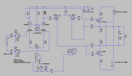
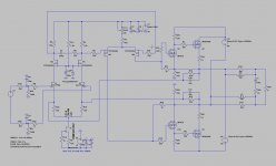
I have change the present version such that the miller capacitance is no more a issieu, I have cascode the VAS, that way the LTP see only once the input capacitance of 170 pF
giving much more bandwidth and lower distortion.
regards
I have change the present version such that the miller capacitance is no more a issieu, I have cascode the VAS, that way the LTP see only once the input capacitance of 170 pF
giving much more bandwidth and lower distortion.
regards
Attachments
That looks good Kees. What is purpose of the irf9610's like that?
The irf9110 are now in sascode to remove the miller capacity, this way the grounded gate mosfet do the amplification and the other buffering, read about cascodes on wikipedia.
Cascodes has high impedance and when limit that we get width bandwidth, last is the case here.
regards
Hmmm sascode in previous post, a new topologie?.
Oke serious, I have uge overshoots on top of the LTP and gates of VAS.
it is in simulation, the output signal looks good, but I have expericence that a overshoot is not good for the sound quality, it sounds cold, but the amp in real do not sound bad, but I go measure in real that overshoots.
Someone tips what to do to remove it?, i have try all things I did now etc.
Attachments

Overshoot
Kees,
If you intend to keep the cascode, you could substitute U3 and U2 for low power FETs. To correct the overshoot try to use a series resistor with C3/C4.
And (or) try a RC network on the drains of M1/M2 and U4/U5.
Good luck!
Kees,
If you intend to keep the cascode, you could substitute U3 and U2 for low power FETs. To correct the overshoot try to use a series resistor with C3/C4.
And (or) try a RC network on the drains of M1/M2 and U4/U5.
Good luck!
Kees,
If you intend to keep the cascode, you could substitute U3 and U2 for low power FETs. To correct the overshoot try to use a series resistor with C3/C4.
And (or) try a RC network on the drains of M1/M2 and U4/U5.
Good luck!
Hi Piersma
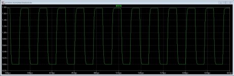
The problem is not the output, there the signal is perfect, an nice 100 Khz square, but when measure in real time the overshoots are not present on my oscilloscope, just a little.
Maybe just the simulation is the problem, I go try with ltspice in stead of multisim.
I go test your tips thanks.
regards
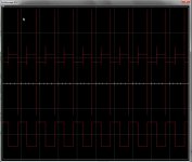
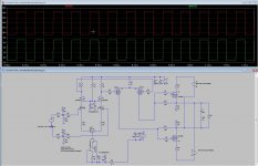
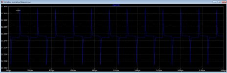
I have done now a sim in ltspice, also here a ringing signal, but in real time on workbench i have not much trouble, so the sim has maybe a wrong model or the capacitance is wrong simulated.
output is oke, distortion oke.
Last picture you see the ltp on top and the output below who is oke.
regards
output is oke, distortion oke.
Last picture you see the ltp on top and the output below who is oke.
regards
Attachments
I have tryed all the possibillities for remove the overshoot from the ltp output, on the end it is not present anymore and so I think it will not have impact on the sound, as is told in a design handbook where ltp are responsable for this peaks and capacitances.
here a link to a nice pcb cad program, it imports eagle perfectly.
TARGET 3001! | PCB Design Software - Electronic CAD/CAE | IB Friedrich
here a link to a nice pcb cad program, it imports eagle perfectly.
TARGET 3001! | PCB Design Software - Electronic CAD/CAE | IB Friedrich
Well the problem is the impedance of the LTP to driver section, when I use 10k resistors for ltp and big swing there then with a source follower I get good signal, and no overshoots.
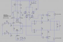
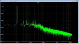
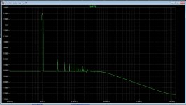
Here a test with a amp, without feedback, or only local feedback, I was supprised with the HD output, that is quite low without a overall feedback.
So I need a impedance converter there, a small N mosfet into a P mosfet and overall feedback, but a cascode with upper N and lower P mosfet do that work
but also implement it in the circlotron section is a better way, like compound.
regards
Attachments
The feedback is the reason that things go wrong, well not really wrong, it is part of feedback action, I need to implement it such that the current stays under the idle current of the LTP, this is with full power of the amp.
when change that this way the amp is a lot better in respons, special with high power output.
The overshoots are part of that feedback beacuse the feedback cause it, however it is just 300 mV or such and has no impact, it can not be removed except when remove the feedback, also voltage feedback cause it as part of it, I tested,.
regards
Attachments
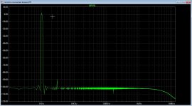
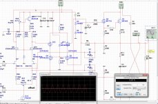
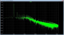
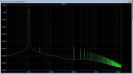
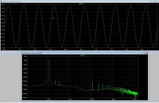
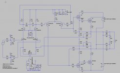
Well after I did seek more and special the oscillations, I did put in two coils in the schematic and simulate again, the extra driver version did give a supprise, so low HD is that true, the coils did cause that much better spec.
Last two photo,s are super follower configuration in output section aka Sziklai pair with P mosfet as power output, when go N mosfet in this case I need to flip voltages for all sections, and change the preamp fets also, did give also nice respons..
later test again.
Last two photo,s are super follower configuration in output section aka Sziklai pair with P mosfet as power output, when go N mosfet in this case I need to flip voltages for all sections, and change the preamp fets also, did give also nice respons..
later test again.
Attachments

Kees
Nice results ! , I like version with extra IRF610 drivers , that graph look incredibly clean !, what is the OPS-IQ ?
Best Regards
Nice results ! , I like version with extra IRF610 drivers , that graph look incredibly clean !, what is the OPS-IQ ?
Best Regards
I agree that some great progress has been made. The latest amp looks like a nice one. Looking forward to seeing it as a PCB.
Banat and X
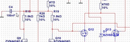
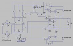
The second version where there are ifrp9240 mosfets did also well, because it is a drain follower it can be sound more warm, that is a experience I have with only plate followers in tube world, however there was no feedback here I have because without it do not well, mosfets have big amplify factor and speed.
X I have in the clean amp problems with oscillations, maybe a resistor of 22 ohm in the driver drain U9 and U 10 will help, it did in sim.
Put a resistor cap network did make it worse, and caps in the feedback path resistors did also make it worse, a resistor and cap in the zvp diff driver did nothing at all, the oscillations can be because tha amp go easely to above 1 Mhz.
regards
Kees
Nice results ! , I like version with extra IRF610 drivers , that graph look incredibly clean !, what is the OPS-IQ ?
Best Regards
The OPS-IQ is class AB, in the sim it is difficult to see what really happens, I have try tgis approach in real world now by change the pcb and have the same distortions as with the old one, strang also that the ground of the pc do flip the amp.
regards
OLG reduce?
Hi Kees,
was still following here.
I have read something, but have to learn more.
Hi Kees,
was still following here.
How is it possible to reduce open loop gain?- could this stop Oszillation Tendenz?Put a resistor cap network did make it worse, and caps in the feedback path resistors did also make it worse, a resistor and cap in the zvp diff driver did nothing at all, the oscillations can be because tha amp go easely to above 1 Mhz.
I have read something, but have to learn more.
Hi Kees,
was still following here.
How is it possible to reduce open loop gain?- could this stop Oszillation Tendenz?
I have read something, but have to learn more.
I try a drain-gate zobel to limit the mosfet in his bandwidth.
and maybe output zobel will work or a small resistor in the circlotron driver drain to supply.
and if not succeed, try try try again.😀
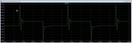
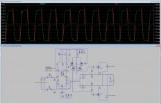
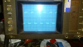
I have managed the unstable behavior with two zobels on the circlotron driver, now it is stable even without load, or with caps and coils, it do well.
signal on the scope picture is 35 volts peak into 4 ohm 20 Khz square.
Maybe a extra zobels on the outputfets will do give extra stability headroom, but when it do well with only this two I think to do not more.
regards
signal on the scope picture is 35 volts peak into 4 ohm 20 Khz square.
Maybe a extra zobels on the outputfets will do give extra stability headroom, but when it do well with only this two I think to do not more.
regards
Attachments
- Home
- Amplifiers
- Solid State
- allFET circlotron