I matched the input transistors. But I will change the transistors anyway. The picture is in post no 2287.
regards Olaf
regards Olaf
Olaf
Thank you about your answer. I could not see the picture.
I suppose there is big differences in your input devices. Can you match pairs?
I suppose it will resolve your problem.
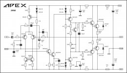
I attached B285 file. It is a commercial product from 80's with this topology. Good sounding in my personal opinion. Also attached my version of SR60
SDS/Ronaldo
Nice THD, is there DC offset on your SR60 simulation? Thank you for your contribution on this prototype.
Regards
I matched the input transistors. But I will change the transistors anyway. The picture is in post no 2287.
regards Olaf
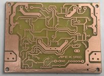
Can you post picture of bottom side pcb?
Regards
Hi Mile, thank you for your attention. I'm sure I have some error in it or I've mistaken the transistors. But I'll find it.
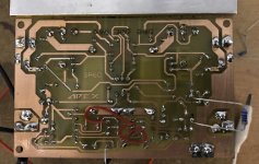
Here is a foto. The quality of the pcb is not so good - my printer is defective and I had to take another one ... Hard times 😉
regards Olaf
Here is a foto. The quality of the pcb is not so good - my printer is defective and I had to take another one ... Hard times 😉
regards Olaf
Attachments

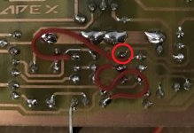
Wow, I checked it again and again! Sometimes you just need another eye. Thank you so much! I'll try it right out tonight and I hope it is the only fault.Olaf, you connected wrong transistor. Look at pic.

I think I need more to take care 🙄. My mistake in the last amplifier Terry has found.
regards Olaf
It is obvious that in real life, this amp is stable.😕 This is a popular DIY amp. I tend to trust the real life result than the simulation.
You can tweek compensation in simulation to get it stable...
Attachments
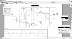
SR60
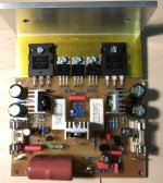
Well, here we are. After eliminating the error with the air wire the amplifier plays - and not bad. The offset is stable at 10mV. All components were very warm, so I went back from +-50V to + -40V. I think it also sounds better so. A very balanced and warm sound, completely unstrained. Maybe the heights could have a bit more transparency at the top. But this is completely subjective and I have not heard enough.
I would say the time to try the little amp is a good time!
The next days I will rework the layout (more distance between the transistors on the heat sink, a small heat sink for the 2SC4793 in the middle, a bit of cosmetics) and then build the second channel and upload the files.
Thanks to dobrivoje for finding the mismatch and to Mile for a new excellent amplifier.
regards Olaf 🙂
Attachments

Well, here we are. After eliminating the error with the air wire the amplifier plays - and not bad. The offset is stable at 10mV. All components were very warm, so I went back from +-50V to + -40V. I think it also sounds better so. A very balanced and warm sound, completely unstrained. Maybe the heights could have a bit more transparency at the top. But this is completely subjective and I have not heard enough.
I would say the time to try the little amp is a good time!
The next days I will rework the layout (more distance between the transistors on the heat sink, a small heat sink for the 2SC4793 in the middle, a bit of cosmetics) and then build the second channel and upload the files.
Thanks to dobrivoje for finding the mismatch and to Mile for a new excellent amplifier.
regards Olaf 🙂
Thank you for building SR60.
Regards
Nice THD, is there DC offset on your SR60 simulation? Thank you for your contribution on this prototype.
Regards
Hi Dobrivoje.
Thank you fr your observation, Maybe I assembly in test board to check results.
I do not got DC offset issue during simulation. I got around 5,5 mV in this test.
SDS/Ronaldo
Hi Dobrivoje.
Thank you fr your observation, Maybe I assembly in test board to check results.
I do not got DC offset issue during simulation. I got around 5,5 mV in this test.
SDS/Ronaldo
Olaf made mistake, there is no DC offset problem.
Regards
You can tweek compensation in simulation to get it stable...
I made the simulation and I did made a few mistakes on my own but mister Mile point out what I did wrong and after I fix my mistakes it works really well, 🙂 I add other stuff like base stoppers and coil and extras as usual, I adjusted to about 20mV single emitter resistor bias adj and a supply of 50V and it has really low THD according to the software results. I did the simulation as a normal use example simulation like you are using only 5W @1KHz sine wave to 8Ω load and THD is 0.001% sometimes 0.000% maximum power with 50V supply can reach about 100W "not going crazy" I mean not need to add more pair of power transistors I will build just as it is no changes 🙂
I'm getting old why I did not see that I made a wrong connection ? I need new glasses 😛
Regards
Juan
Attachments
Last edited:
I made the simulation and I did made a few mistakes on my own but mister Mile point out what I did wrong and after I fix my mistakes it works really well, 🙂 I add other stuff like base stoppers and coil and extras as usual, I adjusted to about 20mV single emitter resistor bias adj and a supply of 50V and it has really low THD according to the software results. I did the simulation as a normal use example simulation like you are using only 5W @1KHz sine wave to 8Ω load and THD is 0.001% sometimes 0.000% maximum power with 50V supply can reach about 100W "not going crazy" I mean not need to add more pair of power transistors I will build just as it is no changes 🙂
I'm getting old why I did not see that I made a wrong connection ? I need new glasses 😛
Regards
Juan
Virtual Zero Distortion Amplifier 🙂
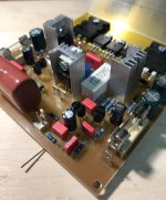
SR60 Part II
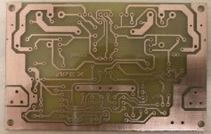
Hi, here is Part 2 of the SR60. Works from the first moment. Very nice sound.
Changes:
- Required heat sink
- Zobel
- Space for 10uF MKP input
- some corrections
The amplifier is definitely a recommendation.
Layout will be uploaded next day (on another PC).
regards Olaf
Hi, here is Part 2 of the SR60. Works from the first moment. Very nice sound.
Changes:
- Required heat sink
- Zobel
- Space for 10uF MKP input
- some corrections
The amplifier is definitely a recommendation.
Layout will be uploaded next day (on another PC).
regards Olaf
Attachments

Hi, here is Part 2 of the SR60. Works from the first moment. Very nice sound.
Changes:
- Required heat sink
- Zobel
- Space for 10uF MKP input
- some corrections
The amplifier is definitely a recommendation.
Layout will be uploaded next day (on another PC).
regards Olaf
Nice work, nice PCB.
Regards
Hi Olaf,
nice work. are you getting those Wima's at a discount?, I see them in your all builds... they are super premium here on Farnell/RS Components. For my Slewmaster build, i had to import them from Canada from a nice gentleman.
reg
Prasi
nice work. are you getting those Wima's at a discount?, I see them in your all builds... they are super premium here on Farnell/RS Components. For my Slewmaster build, i had to import them from Canada from a nice gentleman.
reg
Prasi
Last edited:
Hi, all the Wimas come from a German distributor (www.reichelt.de), where I buy the most components. They are not very expensive and the shop also ship internationally. But I do not know the shipping costs to India, but they are listed on the webpage (also in English).Hi Olaf,
nice work. are you getting those Wima's at a discount?, I see them in your all builds... they are super premium here on Farnell/RS Components. For my Slewmaster build, i had to import them from Canada from a nice gentleman.
reg
Prasi
regards Olaf

olafk you are good man thank you so much for the file ^_^
question, this does not need the output coil right ?
Best Regards
Juan
question, this does not need the output coil right ?
Best Regards
Juan
Last edited:
- Home
- Amplifiers
- Solid State
- Studio Reference Amplifier