Just checked the bins, I probably have enough 5K and 10K .005% S102's to make at least 1 notch filter. Also does anyone know about ULT .01% resistors, I can't find the part number on the web anymore? I found a bag of 100 1K's.
Stunning prices for 0.001% precision resistors, and that's in 500's.
Through Hole Resistors | Resistors | DigiKey
0.005% are expensive, but not crazy expensive. We use them with very good results for precision attenuators (1k-9k-90k-900k).
Stunning prices for 0.001% precision resistors, and that's in 500's.
Through Hole Resistors | Resistors | DigiKey
0.005% are expensive, but not crazy expensive. We use them with very good results for precision attenuators (1k-9k-90k-900k).
We just had to buy 20 or so .001% at 1's price.
In 1975 when we did the first IC 12bit DAC the designer's tech had to make a complete 12bit R2R reference. Vishay sold a DIY kit that you link trimmed by hand under a microscope with a tiny tool. You then had to encapsulate them with an epoxy that had all gas and moisture removed in a vacuum bell jar. They were then baked and remeasured, usually took 5 or 10 to get one good one.
Another source for ultra precision resistors: Resistors - Oil Filled - Epoxy Encapsulated | Ohm-Labs, Inc. I talked to them a while ago. They can make any level of precision. Also told me a story about how the "formula" to make some of the special wires has been lost.
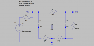
The caps are C0G 1%, the resistors Mini-MELF 0.1%.
My mistake, the filter is not twin-T - it is the Hall network.
Could you kindly post a link to any design details that have been published ?
Thanks,
Patrick
I tend to believe that the attention to detail needed to get a piece of equipment to perform at such low distortion levels tends to result in a better-sounding product. In other words, it may not be the distortion itself per se, but rather that the attention to detail may mitigate other effects that may degrade the sound.
Cheers,
Bob

😎🙂
THx-RNMarsh
Could you kindly post a link to any design details that have been published ?
Thanks,
Patrick
You can find the Hall network theory at either of the two links below:
http://electronicdesign.com/analog/redis...ll-network
http://traktoria.org/files/radio/filter_...filter.pdf
The Traktoria link is better - there are small errors at the ED link.
As to the Gerbers, etc. you'll have to drop Samuel a PM.
Regards,
Braca
Last edited:
Thanks. Already found those.
I was looking for details of Samuel's implementation and (measurement ?) results.
He mentioned in other threads he posted them somewhere at DIYA.
But the search tool did not lead me to the right post(s).
Patrick
I was looking for details of Samuel's implementation and (measurement ?) results.
He mentioned in other threads he posted them somewhere at DIYA.
But the search tool did not lead me to the right post(s).
Patrick
Precision (.001% tol) is a good thing. However, unless the source gen is very freq stable and exactly the same freq as notch filter..... probably doesnt need to be that good tol. Non-inductive wire wound R's have harmonics well below <<-130dB. Maybe we can use them.... a lot cheaper too and more readily available.
THx-RNMarsh
THx-RNMarsh
Thanks. Already found those.
I was looking for details of Samuel's implementation and (measurement ?) results.
He mentioned in other threads he posted them somewhere at DIYA.
But the search tool did not lead me to the right post(s).
Patrick
I think I have them in a folder somewhere. I can dig them up later today for you.
I can't post them but I can send them to you.
Precision (.001% tol) is a good thing. However, unless the source gen is very freq stable and exactly the same freq as notch filter..... probably doesnt need to be that good tol. Non-inductive wire wound R's have harmonics well below <<-130dB. Maybe we can use them.... a lot cheaper too and more readily available.
THx-RNMarsh
It beats sitting down with an ohm meter and 100's of resistors.
I'm also not aware of any published performance figures for this filter. I've built one, but I'm just beginning to gather experience with it.Thanks. Already found those.
I was looking for details of Samuel's implementation and (measurement ?) results.
He mentioned in other threads he posted them somewhere at DIYA.
But the search tool did not lead me to the right post(s).
Patrick
For information, using an RC generator as a source and a digital scope as the readout, I got more than 60dB of attenuation of the fundamental of 919Hz, the latter being the notch filter freq. of the filter with the nominal part values, i.e. without the tuning resistors.
I also improvised a tuneable version of the filter as per Fig. 1 of the Kuhn's paper using caps with 5% tolerance, and tested it at three frequencies in the tuning range around 1kHz in order to see whether the notch depth varies with frequency. Within the rather high uncertainty of the method, the notch depth remained around 40dB at all three frequencies.
With a due caution that these were only crude measurements, I would say that this is not a bad performance.
Regards,
Braca
> I can't post them but I can send them to you.
I'll send you my email address by PM.
Many thanks,
Patrick
I'll send you my email address by PM.
Many thanks,
Patrick
You can find the Hall network theory at either of the two links below:
http://electronicdesign.com/analog/redis...ll-network
http://traktoria.org/files/radio/filter_...filter.pdf
The Traktoria link is better - there are small errors at the ED link.
As to the Gerbers, etc. you'll have to drop Samuel a PM.
Regards,
Braca
Using the corrected write up a simulation only gives a ~46dB notch, Rs = 0 and Rl = 10**9. What am I missing?
Using top picture all caps are .01u, R2 is two 5k resistors (k = .5) and R1 has to be ~13.2*5k not 10k to get a notch of ~45dB???
Last edited:
OK using the values for his lightbulb oscillator and wallking the two pots back and forth a few times I could get -60dB at exactly 1kHz. The values for the two lower resistors are fairly far apart. Still missing something.
Referring to the notation in the schema enclosed, ratio of R1 to R2 must be 12 for optimal performance.Using the corrected write up a simulation only gives a ~46dB notch, Rs = 0 and Rl = 10**9. What am I missing?
Using top picture all caps are .01u, R2 is two 5k resistors (k = .5) and R1 has to be ~13.2*5k not 10k to get a notch of ~45dB???
I'm also enclosing my LtSpice model of the filter.
Regards,
Braca
Attachments
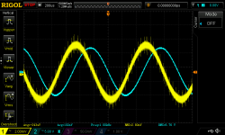
I've just completed the Groner filter by tuning it for a nominal frequency of 1kHz. The tuning is effected by soldering several extra resistors onto the pads provided on the board (I'll post the values if there is interest).
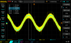
I connected the filter at the output of the 1kHz state filter oscillator mentioned previously, and obtained the waveforms of the first oscillogram enclosed. There is an attenuation of more than 60dB, but since there is also phase difference between the input and output, the oscillator and filter frequencies were apparently not in tune. Using the trimmers provided on the oscillator for fine tuning its frequency resulted in the second oscillogram enclosed. The phase seems to be right now, and the attenuation is at a maximum.
Taking the RMS input and output voltages at their face values results in an attenuation of 75dB.
Note that the filer and the oscillator are on the bench, no casings, BNC connectors, etc.
Regards,
Braca
Attachments
Thanks it makes sense now, I had a different idea of what was meant by tuning range. Also there is some confusion about the ratios in the write up, R2 was drawn as the value of the pot not 1/2 of it and the factor is 12 not 13.2
Last edited:
It beats sitting down with an ohm meter and 100's of resistors.
there is no need for .001% tol.
-RNM
I've just completed the Groner filter by tuning it for a nominal frequency of 1kHz. The tuning is effected by soldering several extra resistors onto the pads provided on the board (I'll post the values if there is interest).
Using the trimmers provided on the oscillator for fine tuning its frequency resulted in the second oscillogram enclosed.
Regards,
Braca
Since this will be used for distortion measurements.... any distortion tests on filter??
-RNMarsh
Bruce Hofer's presentation seems to indicate SMT thin film resistors of larger package sizes are good performers, esp the lower tempco parts. I believe at least one of OPC's "The Wire" headphone amp projects here used Susumu RG resistors and the measurements looked spotless. I'd try those in 1206 instead of MELF which I hate because they roll all over the damn place.
- Home
- Design & Build
- Equipment & Tools
- Low-distortion Audio-range Oscillator