Hello Everyone:
Sorry I just saw this discussion, but I'd like to set the record straight about CLIO Pocket's THD measurements. They are spot on. You just have to hit the bucket correctly - the same as with any other FFT based distortion measurement. 🙂
The bucket I'm referring to is actually called a FFT bin. A FFT measurement is made up of hundreds of these bins that "catch" the magnitude and phase data from the FFT transform. Then it's just connect-the-dots from bin to bin to draw the trace on your screen.
If you choose a frequency that doesn't hit the center of a bin, that fundamental or harmonic will miss the bin (or be sliced by the windowing into a smaller, thus under-represented sample) and you'll get an understated THD measurement.
Audio Precision vs. CLIO Pocket THD
View attachment 575390
YouTube Video
CLIO Pocket THD Measurement
Thank you for clarification. But Farina distortion measurement is more informative. Clio Pocket has Sweep stimulus, I do not see no problem insert it into the system.
lholland one more question. How to make solid measuring under 40 hZ, for example if I want to know frequency bass port. Join people here, their poor results.
Thank
This forum is so cool - you're from Slovakia! One day I'm going to visit your beautiful country. Anyway...
CLIO Pocket and the Farina Method
I'm going to forward your suggestion to Audiomatica today, but I have a feeling in accord with previous posts in this thread that this may be a bit beyond their target for this product. Nevertheless, IMO, if this feature is easy to implement it would not encroach on CLIO FW at all.
And you are so right - the Farina method of isolating the distortion components from a log swept sine is much more informative because with a single measurement you can get full bandwidth distortion plots for each of the harmonics until they become buried in the noise floor.
There are some compromises involved with the Farina approach such as the lack of isolation of one type of distortion from another (anything that lands at the same time as a harmonic is considered a harmonic), fairly high noise sensitivity that makes it unusable in some measurement situations (mainly acoustic), and the fact that acoustic reflections that land at the same time as the harmonics are also incorrectly counted as distortion products. For these reasons, each measurement platform I'm aware of that includes the Farina method also includes a more robust method (examples: Audio Precision and ARTA).
BUT, the Farina method does something cool in that you instantly can see distortion related problems in your log sweep measurements simply by looking at the impulse response or better yet, an ETC of same due to its much higher sensitivity. Ivo Mateljan, the brilliant ARTA designer included this illustration in his manual using an IR:

I recently wrote a paper that pretty thoroughly gives the background to the Farina method without really trying to and without using fancy math! It's also a full introduction to CLIO FW's distortion measurement facilities: Making Good Measurements - Learning to Recognize and Avoid Distortion.
Low Frequency Measurements
I'd love to help figure out the issue you're having making LF measurements, but I don't quite understand the trouble you are having. Here are a few suggestions that should help:
1. Use the lowest possible sample rate of 48kHz so that the FFT spends more time at LF, thus increasing S/N, thus giving you cleaner and more accurate results.
2. Use the highest possible FFT size of 65536 for the same reason.
3. Read Measuring Loudspeaker Low-Frequency Response by Joe D'Appolito, it'll make your day. 🙂
Last edited:
Hello:
I just posted a tutorial that explains how to use CLIO Pocket (or any FFT analyzer that offers the Flat Top window function), to measure THD with an external sine wave generator.
YouTube Video
CLIO Pocket THD Measurement (2 of 2)
I just posted a tutorial that explains how to use CLIO Pocket (or any FFT analyzer that offers the Flat Top window function), to measure THD with an external sine wave generator.
YouTube Video
CLIO Pocket THD Measurement (2 of 2)
Hello:
I just posted a tutorial that explains how to use CLIO Pocket (or any FFT analyzer that offers the Flat Top window function), to measure THD with an external sine wave generator.
YouTube Video
CLIO Pocket THD Measurement (2 of 2)
Thank you for tutorial. Ihollan, Kaiser7 windowing is no better that FlatTop?
I would love to ask, you'd have to do manual measurement of near-field?
This measurement is only what has appeared here
Attachments
Thank you for tutorial. Ihollan, Kaiser7 windowing is no better that FlatTop?
I would love to ask, you'd have to do manual measurement of near-field?
This measurement is only what has appeared here
FFT Windowing
There are hundreds of different types of FFT windowing functions that have been developed over the years. The reason behind each was application specific, meaning the designer wanted to see something in the acquired data that wasn't shown or wasn't clearly shown using existing window functions.
In audio we have just a handful of applications that require windowing and the state of our art has distilled this universe of available functions down to a subset fewer than about 10. Just as in other disciplines, the windowing most appropriate for audio depends on what you want to see.
I have found the need for only (3) types of windows for 99% of audio measurements:
1. "No Window, Rectangular, Uniform, etc". This is what you chose when the FFT analyzer receives data that fits perfectly within the FFT bins in use. This kind of stimulus has to be designed specifically for this purpose and is almost always the superior way to make measurements.
2. "Hanning". This is what you choose when you need a balanced perspective of an unknown signal received by the FFT analyzer. By balanced, I mean that the magnitude and phase of the data is reasonably accurate and that the uncorrelated data received (noise) is substantially reduced in the measurement.
3. "Flat Top". This is what you choose when you want the highest possible magnitude accuracy at the expense of noise suppression.
The other windows generally fill the 1% need for specialized analysis of electrical domain equipment.
The Science of Measurement is Threefold
1. You must understand (or model) what you intend to measure, ask specific questions that you want answered about the DUT and finally make predictions as to the most likely answers to those questions.
2. You make the measurement in such a way that it is most likely to produce the most accurate answers to these questions.
3. You interpret the measurement accurately based on a full knowledge of the limitations of the measurement method employed. This is when you answer the questions posed in step #1.
Windowing Sine Waves for THD Measurement
1. We do NOT want to use a windowing function if we are able to make a closed-loop measurement. This means using the analyzer’s output to feed the DUT with a bin-centered sine wave, which in turn feeds the analyzer’s input.
2. We do not care about the noise between the fundamental and harmonics in a THD measurement, we only care about the absolute levels of each. Therefore, open-loop THD measurements should use the Flat Top window function. Open-loop means that an external source, not the analyzer, feeds the DUT with the sine wave.
Near-Field Measurements
I do not understand your question, but it is apparent that you use Ivo’s excellent ARTA measurement software given your mention of the Kaiser7 window function. The ARTA manual is one of the best written measurement system manuals available and has many tutorial style illustrations included. The ARTA website also offers several excellent application note type papers to further your knowledge in these areas. The joy of audio for me has always been found in the learning, and the greater the effort involved in the learning, the sweeter the achievements become. I suggest you take the red pill and see how far the rabbit hole goes! 🙂
Thank you for answer, your video tutorial is very good and easy to understand. Yes, Kaiser 7 I use in Arta, for me best window when I need max resolution in spectrum, distortion mesurement. and I agree that there are many possibilities in the area windowing.
Thus, in my opinion, the idea of Clio Pocket is very good. Good hardware, absolute compatible with software with very good parameters, standard sound card included 250-300E, this does not offer. Easy calibration for absolute SPL is super. and so on.
As to measuring distortion with Sweep. Is it speed, fairly accurate and complex. Is clear, that spectrum or stepped sine is better.
To reflection, would help assist averaging and measurement in near field, of course with long sequence.
My question about near field measurement I thought that the only measurement I found out Clio Manual is what I sent. If you notice, the information below 40 Hz is weak. I think I now why. Measurement techniques know MIB measurement can not always be used. My question is whether it is possible to make solid near field measurements from 10 Hz, like in tutorial D’Appolito.You can write in short, the ideal setting some to be the result than in the manual. Alternatively, if you have a moment as well as some video. Thank you very much for your time.
My question is whether it is possible to make solid near field measurements from 10 Hz, like in tutorial D’Appolito.
Yes. 🙂
As a matter of fact, CLIO Pocket can make better measurements from 10Hz than the majority of other acoustic measurement systems on the market. It's all about signal to noise. Thus we have (2) variables to work with, the correlated signal output from the DUT and the uncorrelated noise from the environment.
The higher the signal, the better the measurement accuracy at the frequencies that have the least output from the DUT. In most cases, that means low frequencies as in your example. But you have a limit - if you go too loud, the DUT will become nonlinear and you will violate the LTI requirement of FFT (or any other measurement format). Any measurement system with the right amplification can get us to that maximum level.
Now... on the other end things - noise - not just any measurement system will do. The intrinsic noise of the audio measurement interface is the hard limit one comes up against. The lower the noise floor, the better. Ultimately we want our measurements to have the highest signal and least noise.
I would love for someone to post a measured noise floor that is less than the following regardless of cost. I was amazed when I first saw this:

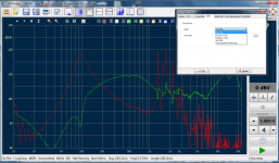
Secondly, CLIO FW and CLIO Pocket have (9) mic input sensitivity ranges with maximum input levels from +40dBV (100V RMS) to -40dBV (10mV RMS). The minimum input level in each of those (9) ranges is 50dB less than the maximum. For example, the -40dBV sensitivity setting will give you good measurement S/N from -40dBV to -90dBV. Here is a demonstration using the maximum and minimum measurement levels made at the -40dBV gain sensitivity:

Using the measurement you referred to for illustration, both the red trace and the green trace fell apart 30dB under their peak readings. If the gain sensitivity had been adjusted correctly, the full 50dB of dynamic range would have been available and both of those traces would have had clean data down to at least 15Hz.
So... What you saw was not a short-coming in CLIO Pocket, it was simply non-optimized gain structure.
A New Video Tutorial on Measurement Gain Structure
I updated the video for clarity, thus the link is updated as well:
Measurement Gain Structure Video Tutorial
Measurement Gain Structure Video Tutorial
It only changes the freq. range (start or stop) when you use the generator independently. It doesn't change the lower and upper freq. when you use logchirp to make measurement (imp, SPL, dbV, etc.). I am using rel.1.4.1 software.
From what i can see, this is possible in clio 11, why not also have it in the clio pocket? How do you protect tweeters from damage when playing the full bandwidth signal at normal or higher drive levels?
From what i can see, this is possible in clio 11, why not also have it in the clio pocket? How do you protect tweeters from damage when playing the full bandwidth signal at normal or higher drive levels?
Good points all around. I have had others ask for user definable sweep ranges in CLIO Pocket's LogChirp module similar to what is currently available in its FFT module.
As far as protecting tweeters during high level measurements, CLIO Pocket can do a very good job with this even without removing or filtering the lower stimulus frequencies from the sweep. The danger to their small voice coils isn't over-excursion (unless you drive the poor thing past its ratings), but thermal damage.
Thermal damage requires high levels for a long enough period of time to cause over-heating. If you measure at a 96kHz sample rate using the smaller 16K FFT length, you will easily avoid thermal problems because the sweep is so quick ((16*1024)/96000) = 0.17 seconds. Of that 1/6th second sweep, only about half that (1/12th second) is spent at frequencies lower than the natural passband of mid and high frequency drivers. This really is overkill and I've found that using the standard 48kHz sample rate with a 16K FFT is more than quick enough to keep things safe. So all is well as long as you stay within the drive level ratings of the DUT.
With CLIO FW v11 you can implement "EQ filters" to modify the LogChirp module's sweep stimulus, but that can be tedious and not the right way to skin the cat. CLIO FW has offered user defined sweep and tone burst control for more than a decade through its Sinusoidal module. That module is so powerful and so unique that you can't get its feature set with anything else in the world that I'm aware of. It also boasts TEF-like S/N capability due to its synchronized gating filters that follow the sweep or tone bursts. This huge S/N advantage also enables accurate distortion plots down to the 10th harmonic.
Don't hold your breath waiting for Audiomatica to add the Sinusoidal module to CLIO Pocket. It doesn't make sense at its price point even if the tiny hardware interface could support it.
With that said, I'm still going to let Audiomatica know I've had another request for band limited LogChirp sweep capability in CLIO Pocket. I totally understand this desire and I will keep pushing for it. 🙂 As explained above, band limiting really isn't needed for high frequency devices, but it is comforting and can be very helpful investigating limited portions of a DUT's passband that you want to drive harder and/or longer than safely possible otherwise.
Last edited:
i thought some tweeters like ribbons were fragile and did not like low frequencys, and using a protecting cap is not as elegant as a user set bandwidth limiting logchirp sweep.
that and possibility to measure harmonic distortions must first be added before i order my clio pocket.
many years ago i used to use clio lite, but sold it when dos got just to old. i sometimes wonder why i sold it cause something i liked a lot were the absolute sound level readings. i have now got tired of soundcard based measurement softwares like arta and all the mess to get absolute readings, and it just does not work! it works ok for relative measurements but i want more, especially for distortion measurements and plots.
i have thought of omnimic too but the sound files on a seperate cd just pulls me of, and the lack of true measured phase
It's pretty easy to set the SPL calibration in ARTA if you have a calibrated mike. Certainly, the built-in calibration in CLIO Pocket is even easier (both SPL and impedance), which is why it's my first go-to when I need a speaker measurement.
At the moment, I'm also using an APx1701, which is the best of the bunch, really excellent integration, but at its price, it damn well ought to be the best.
At the moment, I'm also using an APx1701, which is the best of the bunch, really excellent integration, but at its price, it damn well ought to be the best.
please teach me how to do it, i use a sound level meter to calibrate and check levels, i calibrate mic sensitivity at 94db and when i then run a test at the same level the readings differs several dbs in arta.
and why does not a change in output volume within arta settings give me different db reading? it does not matter if i decreases the output level to -20db, i get the same db reading as set with output to 0db
and why does not a change in output volume within arta settings give me different db reading? it does not matter if i decreases the output level to -20db, i get the same db reading as set with output to 0db
Is ARTA giving you SPL readings or voltage to SPL sensitivity readings? Both are very useful but can lead to a lot of confusion.
celef, do you have a calibrated mike? What interface or sound card are you using? I can walk you through it.
i thought some tweeters like ribbons were fragile and did not like low frequencys, and using a protecting cap is not as elegant as a user set bandwidth limiting logchirp sweep...
All drivers, ribbon or otherwise have (2) failure modes. One is long-term over-heating and the other is short-term over-excursion. I covered the far more common threat of over-heating in my last post, so I will go into more detail concerning the latter in this reply.
Over-excursion occurs with peak-to-peak motion of the moving element travels beyond its physical limits. This excursion limit is an absolute distance and does not change based on the frequency at which it occurs. Over-excursion initially results in increasing distortion, and if unabated can cause permanent damage.
I’m about to say something that may surprise you, but it’s simple physics and thus true: If you select a given voltage level to drive the transducer that is within the peak capability of its normal operational passband, the lower frequencies of the measurement sweep stimulus will not cause further transducer excursion, thus no damage. This is because of the natural 12dB per octave (or more) rolloff of the driver.
Why? Physics tells us that the amplitude (excursion required for constant SPL) is inversely proportional to the square of the angular frequency. Generally speaking, this means that as you go down in frequency you have to increase the peak-to-peak excursion of the transducer to maintain the same SPL. The math is very simple; (higher frequency/lower frequency)^2 = increase in excursion.
Example: say you have a tweeter that is flat from 15kHz down to 2kHz. How much does its excursion increase from 15kHz to 2kHz to maintain that constant SPL?
Answer: (15000/2000)^2] = 56.25 times more excursion at 2kHz! This of course also means the tweeter travels 56.25 times LESS at 15kHz relative to 2kHz, which is the reason that peak limiting is far less important at the highest frequencies than RMS (thermal) limiting.
Now let’s convert our excursion math into dB per octave: 20log [(2/1)^2] = 12dB per octave. That means all loudspeaker drivers must increase their excursion at 12dB per octave as they go down in frequency to maintain a constant SPL.
Linkwitz said it like this: "Driver cone excursion increases at 12 dB/oct with decreasing frequency for constant SPL, yet the crossover rolls off at only 12 dB/oct which leaves the excursion constant.
IT ALSO MEANS that our example tweeter with a natural roll off under 2kHz at 12dB per octave MAINTAINS CONSTANT EXCURSION at measurement stimulus frequencies under 2kHz. Thus no danger or damage to the driver as long as the voltage applied did not cause over excursion at the lowest frequency within its normal passband (2kHz or whatever lowest frequency specified by the mfg).
IT ALSO MEANS that our example tweeter driven at this same maximum voltage using a sweep that excludes frequencies under 2kHz is no safer from over-excursion.
Try it. 🙂
...that and possibility to measure harmonic distortions must first be added before i order my clio pocket...
You must be referring to distortion plots and not single frequency distortion measurements, because CLIO Pocket does the latter with excellent accuracy.
...many years ago i used to use clio lite, but sold it when dos got just to old. i sometimes wonder why i sold it cause something i liked a lot were the absolute sound level readings. i have now got tired of soundcard based measurement softwares like arta and all the mess to get absolute readings, and it just does not work! it works ok for relative measurements but i want more, especially for distortion measurements and plots.
i have thought of omnimic too but the sound files on a seperate cd just pulls me of, and the lack of true measured phase
ARTA rocks, but as you say it is so nice to have a calibrated audio interface included with the software. ARTA is much less of a pain if you buy an audio interface that does not have analog gain controls, but is software controlled. That way you can copy CLIO’s method and make various calibrations in ARTA at 10dB intervals and select those in ARTA as you make the analogous changes to the audio interface sensitivity.
Another nice advantage of CLIO Pocket and its big brother, CLIO FW is that the audio interfaces can accept up to 100V RMS (40dBV). That’s a huge convenience.
In my opinion, you can achieve great results in almost all areas of acoustic and electrical measurements with CLIO Pocket if you supplement it’s abbreviated features with empirical study. Such as the above example of the physics of vibrating masses vs. sound pressure to avoid the "need" of frequency limited sweeps. What I mean by empirical study is to buy a bunch of RCD's (really cheap drivers) and carefully blow them up while observing levels vs. time at those levels vs. the manufacturer's lies specifications. 🙂
Secondly, also in my opinion, anyone that truly loves the various disciplines of applied science involving acoustic and electrical measurement should do whatever it takes to buy CLIO FW. I have and use ARTA, Audio Precision APx515 with almost all options (which would be SO much nicer with Stuart's APx1701!), SysTune Pro, Smaart, FIR Capture (just out of beta!) and various modeling packages and if I had to choose only one, it would be CLIO FW.
I’m not trying to sell anything and as you can see by the length and detail in my posts I love learning and sharing what I learn. I consider it an honor to interact on what is the largest audio forum I’ve ever seen. If I do cross any lines or it appears I’m trying to sell stuff, it will be an accident and please let me know specifics so I can avoid it in the future - thanks. 🙂
Last edited:

Your input here is greatly appreciated and, IMO, extremely helpful, for which I thank you.
I wish the 1701 were mine! Sadly, it's just on loan.
I wish the 1701 were mine! Sadly, it's just on loan.
Its interesting that the 1701 doesn't have a supply for Gras/B&K type microphones. You still need to buy that supply for another $2-3K. That is all an expensive game. Their right that testing Bluetooth speakers and noise cancelling headphones is what we do today. I'm not sure how the 1701 helps.
Is Clio pocket or Clio FW able to do two port differential measurements? In testing headphones for noise reduction I use an external microphone as a reference and look at the gain/loss and phase between the internal and external microphone. For that matter is it possible with Arta?
Is Clio pocket or Clio FW able to do two port differential measurements? In testing headphones for noise reduction I use an external microphone as a reference and look at the gain/loss and phase between the internal and external microphone. For that matter is it possible with Arta?
thank you all for your replys! very much appreciated!
my simple test setup contains a preem mic-12 preamp, a number of selected panasonic mic capsules, some linkwitz modded, and the inbuilt soundcard of a standard laptop. the frequency errors and distortion levels are low in this setup compared to my diy loudspeakers under test. i also use a simple sound level meter SL 322 Ljudmätare for absolute levels.
i can get absolute readings in arta in spectrum analyzer and spl-meter mode, but not i impulse response mode, no matter what i do.
i must go now, my family wants me for going shopping, but i will get back later
Its interesting that the 1701 doesn't have a supply for Gras/B&K type microphones. You still need to buy that supply for another $2-3K. That is all an expensive game. Their right that testing Bluetooth speakers and noise cancelling headphones is what we do today. I'm not sure how the 1701 helps.
You can do much of what the 1701 does with a collection of other boxes, but the advantage here is integration and inherent calibration. I haven't done any Bluetooth measurements with it yet, but I did some headphone work, and it was remarkably easy to set up and get quantitative absolute data. The mike interface doesn't have 200V, but it does have options for 48V or constant current, and it has TEDs compliance, so you can use mikes with equivalent performance but lower cost than the B&Ks (I'm thinking PCB's mikes, for example). Spendy for sure, but two low distortion low noise 100W amps, two low distortion low noise mike preamps, and TEDs, along with the integration and interface ease make the $3k price look pretty reasonable.
I still go to the CLIO Pocket first for basic measurements, because talk about easy to use, and the results are trustworthy.
- Home
- Design & Build
- Equipment & Tools
- CLIO Pocket