Just keeping my subscription to this thread as I accidentally killed it!
Thanks everyone for all the great Info!
Thanks everyone for all the great Info!
How about JJ's EL509 with octal socket: JJ EL509 / 6KG6 JJ Electronic - Powertubes: Pentodes Tubeampdoctor
I have built two amplifiers (circlotrons) with those and the performance is equal to PL519.
I have built two amplifiers (circlotrons) with those and the performance is equal to PL519.
Unfortunately JJ used the same poor 6L6 basing for their EL509, so not a very good choice for the 700 V B+ Alastair E mentioned.
Last edited:
Also the jj el509s are very expensive. On the Bay I average about $15 ea for 6kn6s and $10 for 42kn6. And those are nos American tubes not furrin junk.
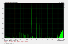
Quoting myself 😡😀 but I will fulfill what I promised (at last ...): here's a FFT measurement (distortion) with 6FQ7. I noticed the following, with lower filament, we have less higher order HD. With more heater power, we have less 3H but far worse higher order HD. For preamps we don't use maximum emissions, so we can opt to choose less heater power. I've already noted this in FFT readings in my amps, but here is to confirm that. A little reduction from 6V3 will show some benefits for high order HD. And some people says that tubes have less noise with a little less heater power...........
In section one (the high-µ), is impossible to match. With low heater, the curves become more J-shaped. With high heater, the curve become more /-shaped. I bet some HD (distorition) change, maybe even dramatically, but I prefer to play with a preamp and my FFT first...
In output section, the change is small, but the J-/ behaviour is the same. is easy to see when the tracer are making the curves.
Interesting...
For output tubes will be more difficult to reduce heater power, unless one are using a PL509 with conservative output power, my case with my own PP amp: I use 34V instead 40V in heater.
Attachments

Have a few questions about the 6hj5 tube. Being a 25w tube and having a g2 max voltage of 220V, it would appear that I would be limited to around 13W in a PP triode if using a Lundahl 9202 wired for 6.5k primary, leaving g2 with a little safety margin with a B+ of around 200V. I was hoping for closer to 20-25w and so I am left seeking out other options. Schaded 6hj5 would allow me to fix the g2 voltage, but I am ignorant of whether or not I can raise the plate voltage in an effort to gain power. Would it be doable to have a schaded 6hj5 with a plate voltage of 300, while keeping the g2 voltage at 200? With a fixed bias voltage of 200v, is g2 affected by increased voltage and swing seen by the plate? Would this create heat issue for g2?
g2 ratings are higher when the g2 is tied to plate as in triode....
tubelab has done this,.i hope he chimes in....or look at his postings...
tubelab has done this,.i hope he chimes in....or look at his postings...
I have read similar statements in a couple threads. I like the idea of keeping it triode, at least to start, but g2 is the big unknown.
The 6HJ5 I tested here is fairly consistent at 1/20 of plate current showing up as screen grid current in triode mode. So 24 Watts of plate diss. would give only 1.2 Watts of screen grid diss., well below the 6 Watt rating. (that ratio depends on the grid 1 to grid 2 alignment, so some small variation may occur, but nothing like 5X)
I test the 6HJ5 routinely on the curve tracer, in triode mode, with 400V max on the plate without a problem. And I just did a test at 650V on the plate/screen and no problem. That's the most I can get conveniently on the curve tracer.
The screen grid socket pins are next to the grid 3/beam former pins, which would normally be at cathode potential. So that is possibly a limiting factor for max plate/grid2 voltage. (beside internal grid2 to grid1 isolation.) I would put a 220 Ohm 1/4 Watt resistor between plate and grid2 for safety. That will only drop a few volts in normal operation, but will fuse out if something goes wrong.
Last edited:
I have not tried the 6HJ5's in triode, so I can't say how they would hold up to excessive screen voltage. In pentode mode with some "Schade" feedback applied, they work just fine with 150 volts on the screen and 600 volts on the plates, and produce 125 watts into a 3300 ohm load. I made 3 of Pete Millett's Engineers Amp wired to operate under these conditions, published the modifications needed in the original thread, and at least 10 other people built the 125 WPC version. Nobody was complaining of blown tubes, and my amp still has the original tubes in it despite being used as a guitar amp set on KILL!!!!
It has been stated here and in many other places that you can exceed the screen grid voltage rating of a tube in triode mode. This has not been true in many of my test amps, and sweep tubes are where this rule breaks down. Yes, when you are playing music the screen follows the plate, and the plate eats most of the current. This is not when the tubes blow up.
When the amp is idling with no music playing the screen grid is at the same potential as the plate. The tube does not know if it is wired as a triode, pentode, or even UL. G2 and the plate are both at near B+ potential. Many tubes will eat this without a problem, but there will be some that exhibit bias creep......the idle current will just slowly rise. Then one day the tube runs away and blows up.
On the usual 6L6GC, or KT88 the runaway comes slowly, often you hear a faint hum in the speaker, then notice the red plate, and can pull the plug before something bad happens. This is not the case with a sweep tube.....G2 has much more gain, hence the lower voltage rating. Once the runaway starts its a few seconds from hum to a big fireball inside the tube, unless a fuse blows somewhere first.
Years ago I built a triode P-P amp using 6LW6's. I started out with a B+ of just under 400 volts and was getting 40 or 50 WPC (don't remember exactly). It sounded real good and worked flawlessly for several months, then one day it went ZAP, Poof, gone. One tube had arced, which blew the line fuse. A new tube, and it was live again....for a while. After three tubes blew in this manner, I swapped out the power transformer and ran the amp on about 330 or 340 volts. It took a while, but eventually it blew another tube, so I gave up and dismantled the amp.....6LW6's are NOT cheap....They will also crank out 250 watts per channel on nearly 700 volts....with 150 V on the screen.
How much will the 6HJ5 eat on its screen? I don't know. Some sweep tubes like the 6CD6 will blow up at 250 volts. Some can stand 350, but I haven't met any true sweep tube that can reliably work at 400 volts. Some examples can, but other tubes of the same number will fail. This depends on how carefully the internal elements were aligned when the tubes were built, and how much mishandling they have seen in the 50 years since then.
Most of my sweep tube work has been in pentode mode since my early triode experiments ended with blown tubes. A sweep tube with "Schade" feedback can sound excellent, and give triode like qualities with the big dynamics of a pentode. Most of my pentode testing with true horizontal sweep (line output) tubes has revealed that most of them work best with 150 volts on the screen. A few benefit from a few more volts (up to 200 on mostly older types) and some like a bit less voltage.
Note that some of the real old sweep tubes do not have a super sensitive screen grid, and need more G2 voltage. The 6BG6 is called a sweep tube, but it is really a 6L6GB in disguise, and therefore needs 350 volts or so.
Tubes designed for vertical sweep (frame output) are really audio tubes in disguise, as they operate as a Class A audio amp, but at one frequency only, 60 Hz in North America, 50Hz most everywhere else. The pentode versions of these tubes need 300+ volts on the screen to work at all. Many of them are 6V6 derivatives.
Screen drive, Crazy Drive, or Twin Drive can work on sweep tubes, but it is also possible to blow a screen drive unless provisions for limiting the drive current are included in the design.
I can't imagine 650 volts on the screen of any sweep tube for more than a few milliseconds being a good thing. In fact I don't think I would go there on a KT88.
Want to run 400 to 500 volts in triode, use KT88's. My Electro Harmonix versions (about 10 years old) start to show signs of bias creep as I got near 500 volts. 6 out of 8 tubes convinced me to stay below 500 volts....In fact my amp runs 465 volts.
Want to run 750 volts in triode? Use 7403's....If you can find any. Check out the triode curves on these guys. They sound real nice too.
It has been stated here and in many other places that you can exceed the screen grid voltage rating of a tube in triode mode. This has not been true in many of my test amps, and sweep tubes are where this rule breaks down. Yes, when you are playing music the screen follows the plate, and the plate eats most of the current. This is not when the tubes blow up.
When the amp is idling with no music playing the screen grid is at the same potential as the plate. The tube does not know if it is wired as a triode, pentode, or even UL. G2 and the plate are both at near B+ potential. Many tubes will eat this without a problem, but there will be some that exhibit bias creep......the idle current will just slowly rise. Then one day the tube runs away and blows up.
On the usual 6L6GC, or KT88 the runaway comes slowly, often you hear a faint hum in the speaker, then notice the red plate, and can pull the plug before something bad happens. This is not the case with a sweep tube.....G2 has much more gain, hence the lower voltage rating. Once the runaway starts its a few seconds from hum to a big fireball inside the tube, unless a fuse blows somewhere first.
Years ago I built a triode P-P amp using 6LW6's. I started out with a B+ of just under 400 volts and was getting 40 or 50 WPC (don't remember exactly). It sounded real good and worked flawlessly for several months, then one day it went ZAP, Poof, gone. One tube had arced, which blew the line fuse. A new tube, and it was live again....for a while. After three tubes blew in this manner, I swapped out the power transformer and ran the amp on about 330 or 340 volts. It took a while, but eventually it blew another tube, so I gave up and dismantled the amp.....6LW6's are NOT cheap....They will also crank out 250 watts per channel on nearly 700 volts....with 150 V on the screen.
How much will the 6HJ5 eat on its screen? I don't know. Some sweep tubes like the 6CD6 will blow up at 250 volts. Some can stand 350, but I haven't met any true sweep tube that can reliably work at 400 volts. Some examples can, but other tubes of the same number will fail. This depends on how carefully the internal elements were aligned when the tubes were built, and how much mishandling they have seen in the 50 years since then.
Most of my sweep tube work has been in pentode mode since my early triode experiments ended with blown tubes. A sweep tube with "Schade" feedback can sound excellent, and give triode like qualities with the big dynamics of a pentode. Most of my pentode testing with true horizontal sweep (line output) tubes has revealed that most of them work best with 150 volts on the screen. A few benefit from a few more volts (up to 200 on mostly older types) and some like a bit less voltage.
Note that some of the real old sweep tubes do not have a super sensitive screen grid, and need more G2 voltage. The 6BG6 is called a sweep tube, but it is really a 6L6GB in disguise, and therefore needs 350 volts or so.
Tubes designed for vertical sweep (frame output) are really audio tubes in disguise, as they operate as a Class A audio amp, but at one frequency only, 60 Hz in North America, 50Hz most everywhere else. The pentode versions of these tubes need 300+ volts on the screen to work at all. Many of them are 6V6 derivatives.
Screen drive, Crazy Drive, or Twin Drive can work on sweep tubes, but it is also possible to blow a screen drive unless provisions for limiting the drive current are included in the design.
I test the 6HJ5 routinely on the curve tracer, in triode mode, with 400V max on the plate without a problem. And I just did a test at 650V on the plate/screen and no problem.
I can't imagine 650 volts on the screen of any sweep tube for more than a few milliseconds being a good thing. In fact I don't think I would go there on a KT88.
Want to run 400 to 500 volts in triode, use KT88's. My Electro Harmonix versions (about 10 years old) start to show signs of bias creep as I got near 500 volts. 6 out of 8 tubes convinced me to stay below 500 volts....In fact my amp runs 465 volts.
Want to run 750 volts in triode? Use 7403's....If you can find any. Check out the triode curves on these guys. They sound real nice too.
Attachments
Fantastic amount of information. Thank you so much for taking the time. I hope to return with pics of an amp.
same here, 465V on KT-88 (JJ). I assume that your amp is the sound application PP, if so may I ask what the OPT and the idle currents are? (or, what mA would you suggest for the 6,5K trafo)Want to run 400 to 500 volts in triode, use KT88's. My Electro Harmonix versions (about 10 years old) start to show signs of bias creep as I got near 500 volts. 6 out of 8 tubes convinced me to stay below 500 volts....In fact my amp runs 465 volts.
Those voltages I mentioned on the curve tracer for the 6HJ5 in triode are the MAX (or peak) voltages reached during plate curve tracing, not a B+ average. So B+ for an amp would have to be 1/2 that or less. And true enough, the curve tracer only reaches those peaks for a few milliseconds at the peak of the AC power sine waveform for each plate curve trace.
There are some creeping path damage modes for mica insulators from ion bombardment that could make the tube bias drift over time. Not much distance between g2 and g1 on the mica surface. In any case, I would use the 220 Ohm, 1/4 Watt, resistor between g2 and the plate for some worst case protection.
There are some creeping path damage modes for mica insulators from ion bombardment that could make the tube bias drift over time. Not much distance between g2 and g1 on the mica surface. In any case, I would use the 220 Ohm, 1/4 Watt, resistor between g2 and the plate for some worst case protection.
Last edited:
Thanks to this thread I bought a dozen or so 12av5ga to play with a while back. They sound wonderful in push-pull with a 6600ohm OPT, 365v B+, 182v on g2, and a 27.7v white LED array as a cathode load, driven by the front end of Sy's Red light district amplifier. Now that I've tested them on that rig, put them away, moved house a few times, and settled down enough to build again, what would be a nice way to drive these? I'm thinking of concertina feeding a LTP, and directly coupled to the g2's via mosfet followers. I've got Russian equivalent 6sn7, 6sl7, and some 6n1p on the way, in addition to a few other mixed bits to try. Any idea on a good B+ to use? Optimum output transformer impedance? The ones I used for testing are for guitar amp use, so not up to higher power use...
Here's the post copied from the red light district thread-
Here's the post copied from the red light district thread-
Here is a pic of my White Light District... 12av5ga output tubes and the front end is from the Red Light District...
My camera FREAKED OUT with the amp powered up and the white light running... But with this particular LED running it sits at 27.5v... Voltage doubler PSU, unregulated at all. My B+ is at 365v, screens connected to the center tap of the doubler, so they are sitting at 182v... This thing is DEAD SILENT and the tubes draw 33mA each. At full tilt each tube is blowing about 200mA and the LED drob only goes up about 25mV. This is a no-name LED from a chinese shop on ebay, I think it was about 2 bucks. I'm pretty sure this is how I'm biasing my next amp.

Last edited:
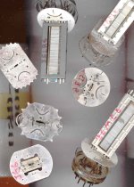
Here are some pics of mica insulators for TV Sweep tubes. Notice the semi-circular groove cutouts around the plate support holes. (plates have been removed) They prevent creeping path mica damage (from ion bombardment) from following the voltage gradient from the plates to something else, on the surface of the mica.
Then check the path length between the g1 and g2 support holes, right next to each other. Zip! Plate voltage on g2 is going to eventually cause problems with g1 bias.
One good reason to use Crazy/Twin Drive instead of triode mode.
Then check the path length between the g1 and g2 support holes, right next to each other. Zip! Plate voltage on g2 is going to eventually cause problems with g1 bias.
One good reason to use Crazy/Twin Drive instead of triode mode.
Attachments
Last edited:
The 6/12BQ6GA got tested here somewhere. Should be similar/exact R values to the 6/12AV5. Close enough for starters.
You can always use a 5K pot for the Rg2g1 and adjust to find the best spot with a PC sound card FFT display (attenuate input to the sound card safely, 1V, AC power isolated). (use a series 1000 Ohm R with the pot, so as to not over current grid 1) Use the same Rg1k resistor as the 12BQ6 for starters, its not as critical.
You can always use a 5K pot for the Rg2g1 and adjust to find the best spot with a PC sound card FFT display (attenuate input to the sound card safely, 1V, AC power isolated). (use a series 1000 Ohm R with the pot, so as to not over current grid 1) Use the same Rg1k resistor as the 12BQ6 for starters, its not as critical.
Last edited:
- Home
- Amplifiers
- Tubes / Valves
- Those Magnificent Television Tubes