Member
Joined 2009
Paid Member
thank goodness it's Friday and a weekend to catch up on sleep - and some progress hopefully on the project !
also - everyone to play nicely - everyone is welcome & encourage to participate here with good suggestions and constructive questions about the project, all of us to be accommodating of everyone's foibles
also - everyone to play nicely - everyone is welcome & encourage to participate here with good suggestions and constructive questions about the project, all of us to be accommodating of everyone's foibles
Member
Joined 2009
Paid Member
More Listening...
I switched over to an ipad for music source. This was much better. It's still not ideal, there are limitations to the quality for sure but based on my experience it does allow some initial feel for the sound. I'm using my B&W floorstander (2.5 way).
There is a familiarity to the sound, reminding me of my TGM1, an AKSA clone. It sounds more powerful though. The mids are the strongest point so far and give the sense that they convey the full texture of the voices and instruments. The bass does not have the visceral punch of my TGM7 & TGM8, it is rather relaxed. This is also very similar to my TGM1 and similar reports from ASKA owners. The overall sound is closest to what I remember of my fathers Sansui. One troubling spot was the treble - there was something a bit bright on some tracks to my ears and I'm sensitive to this. I think I'm running into the limitations of the sound source and a very harsh and bright room - my hobby room isn't too large, has a ceramic tiled floor, bare walls and no soft furnishings - awful in truth. But I am also thinking that the Cdom could be increased in value slightly to bring the sound more in balance with my TGM1 which uses a value that's slightly higher than I'm currently using here on the TGM1i.
more to follow....
Member
Joined 2009
Paid Member
2nd channel
I built up the 2nd channel with the enhanced VAS (EF buffer). Had to tweak some resistors to get the dc offset sorted out again of course. Otherwise no issues.
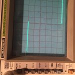
With an 8R load I used the scope probe calibration test signal, 0.5Vp-p 1kHz sq. wave to look at the behaviour of the amp. The sq. wave looks fairly clean to me at this resolution at least.
Sound. Same set up as before. Sound was different of course, cleaner with less texture in the mids. The bass was punchier, definitely less relaxed sound. Jury is still out on the treble until I can get set up with non compressed sound source and better room conditions.
I built up the 2nd channel with the enhanced VAS (EF buffer). Had to tweak some resistors to get the dc offset sorted out again of course. Otherwise no issues.
With an 8R load I used the scope probe calibration test signal, 0.5Vp-p 1kHz sq. wave to look at the behaviour of the amp. The sq. wave looks fairly clean to me at this resolution at least.
Sound. Same set up as before. Sound was different of course, cleaner with less texture in the mids. The bass was punchier, definitely less relaxed sound. Jury is still out on the treble until I can get set up with non compressed sound source and better room conditions.
Attachments

Hi Hugh,Hi Nico,
Perhaps we are seeing Dunning-Kruger?
He means well......
Gareth, congratulations on your latest!
Hugh
Seen you pop in here a few times too. Hope you are doing well and your health has improved.
Member
Joined 2009
Paid Member
I got my drill press assembled. Not sure if this is going to be good enough. It is a Mastercraft from CanadianTire, on sale. I don't know much about these machines, but it seems to me there is way too much wobble on the chuck, it makes a rattling sound when it's running. tightening up the grub screw that presses into a groove on the quill doesn't help, there's too much play in other directions. Maybe this is what you get when you don't spend much but I think I'd rather spend more and get something better. Will have to explore a bit further.
Member
Joined 2009
Paid Member
Pre-amp pcb
I've put the power amp boards aside for now - they will be finalized after further listening tests.
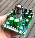
Turning my attention to the last board, the pre-amp containing dual-mono shunt regulated supplies, independent RIAA phono amps and triode buffers.
I found a labelling error on the pcb, the silk screen labels for R704 and R705 were inadvertently swapped around and same for R505 and R501 so I had to de-solder and reinstall.
The input to the shunt regulator is a current source and the sense resistor values depend on the forward voltage drop of the LEDs so I did a 'select on test' for these. Important to tack resistors on the underside of the pcb for sot work since the board is very tight it is a fiddly job removing them from the front-side. I measured around 35mA with 33R sense resistors which is higher than I want so I increased the resistors to 56R which dropped the current to 22mA to keep the power dissipation at a better place.
I measured around 6mA through the triode and 7mA through the RIAA phono amp. The balance of the current, 22 - 6 - 7 = 9mA flows through the shunt regulator. The phono is close to constant current so it doesn't need much headroom from the shunt regulator. The buffer amp doesn't swing much too either so 9mA for the shunt should be plenty.
Didn't do much testing with it today - a square wave input to the triode buffer produced a square wave at the output. But it appears to be at half the amplitude - could be a measurement error or the gain is not where I thought it would be. A finger on the input to the phono amp produced a large mains pick-up signal at the output so can see it's a sensitive thing, as it should be.
I've put the power amp boards aside for now - they will be finalized after further listening tests.
Turning my attention to the last board, the pre-amp containing dual-mono shunt regulated supplies, independent RIAA phono amps and triode buffers.
I found a labelling error on the pcb, the silk screen labels for R704 and R705 were inadvertently swapped around and same for R505 and R501 so I had to de-solder and reinstall.
The input to the shunt regulator is a current source and the sense resistor values depend on the forward voltage drop of the LEDs so I did a 'select on test' for these. Important to tack resistors on the underside of the pcb for sot work since the board is very tight it is a fiddly job removing them from the front-side. I measured around 35mA with 33R sense resistors which is higher than I want so I increased the resistors to 56R which dropped the current to 22mA to keep the power dissipation at a better place.
I measured around 6mA through the triode and 7mA through the RIAA phono amp. The balance of the current, 22 - 6 - 7 = 9mA flows through the shunt regulator. The phono is close to constant current so it doesn't need much headroom from the shunt regulator. The buffer amp doesn't swing much too either so 9mA for the shunt should be plenty.
Didn't do much testing with it today - a square wave input to the triode buffer produced a square wave at the output. But it appears to be at half the amplitude - could be a measurement error or the gain is not where I thought it would be. A finger on the input to the phono amp produced a large mains pick-up signal at the output so can see it's a sensitive thing, as it should be.
Attachments
Last edited:
Member
Joined 2009
Paid Member
Eagle pcb layout fail...
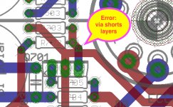
I tracked this down to a pcb layout error. It looks as if I have an errant via shorting out the front-back traces where it shouldn't. The ERC says there is no electrical error (which is why I didn't see this before tape out - must be I made a mistake in use of the ERC tool).
The solution is to drill-out the via and remove the short. A small wire link will be needed between a pair of adjacent through hole pins on the back-side. It looks like a trivial repair but I'm disappointed in the lack of perfection.
- a square wave input to the triode buffer produced a square wave at the output. But it appears to be at half the amplitude - could be a measurement error or the gain is not where I thought it would be.
I tracked this down to a pcb layout error. It looks as if I have an errant via shorting out the front-back traces where it shouldn't. The ERC says there is no electrical error (which is why I didn't see this before tape out - must be I made a mistake in use of the ERC tool).
The solution is to drill-out the via and remove the short. A small wire link will be needed between a pair of adjacent through hole pins on the back-side. It looks like a trivial repair but I'm disappointed in the lack of perfection.
Attachments
Member
Joined 2009
Paid Member
PCB fix
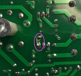
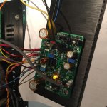
A couple of minutes and it's fixed. Dremmel out a hole to remove the via. Test with DMM to ensure it's good and a close look optically for debris etc. Then a small wire link soldered on the backside.
fyi - the pcb mounting spacer (hexagonal nylon) you see in this image is right underneath the valve socket. You have to install the mounting screw from the top of the pcb before soldering in place the valve socket. The valve socket has a central hole that allows a hex wrench to be inserted to tighten up the mounting screw. The reason I added a pcb support here is to hold the valve base very rigidly to the chasis without any strain on the pcb itself. Inserting and removing valves puts a fair amount of stress on the socket and I didn't want this to stress the board which is held by similar supports at the 4 corners. It's nice and solid when built this way.
Attachments
Last edited:
Member
Joined 2009
Paid Member
And now the gain of the triode buffer measures around 0.96 which makes sense. With a 2k8 load this drops to 0.88, consistent with an output impedance of over 100R, as it should be since I have a 100R build-out resistor on the cathode.
And I exchanged my drill press for a new one. This one performs much better and it allowed me to drill a number of neat holes in a new baseplate today. The holes are sooooooo much more accurate than a hand held power drill that I think this might actually work.
All is good in the land of TGM1i again 😀
Last edited:
Member
Joined 2009
Paid Member
You have to use the yellow handled one's, they improve the shape of the cut wire to ensure electrons don't escape into the surrounding air. This improves the low level micro-detail at high frequencies 😀
Member
Joined 2009
Paid Member
Dry fit
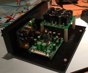
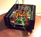
I did a dry fit of the boards and chasis to see how things are coming along after getting some drilling finished. It's pretty crowded as expected. The photo shows just one heatsink, there are of course two of them, one on each side and a power amp on each one of them. The pre-amp goes between them on the base plate with headroom for the valve. The power supply goes behind it and is elevated so that the power transformer can sit underneath it.
I discovered that the extra winding of insulated wire on the trafo for the valve heater increases the height of the transformer too much to fit comfortably underneath the psu pcb so I'm going to replace this wire with proper magnet wire which is much thinner; I can't raise the pcb as there's no room. But it's a chance to order a few parts to fix up some changes I want to make - I found a couple of capacitors on the pre-amp that are being used above their maximum voltage specification and need to be uprated.
Attachments
Last edited:
Member
Joined 2009
Paid Member
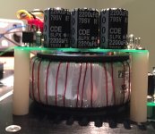
I bought myself some magnet-wire and rewound the heater supply winding on the power transformer to create the necessary 3mm or so of clearance between the underside of the power supply pcb and the metal mounting plate holding the power transformer to the chassis. The photo doesn't show this separation properly but it gives the general idea !
The power supply is all wired up now, including both the protective earth and a mains voltage selector switch which I've mounted in the bottom of the chasis.
The power supply is all wired up now, including both the protective earth and a mains voltage selector switch which I've mounted in the bottom of the chasis.
Attachments
Member
Joined 2009
Paid Member
Thanks for the encouragement guys 🙂
Moving closer to something ready for me to hook up a better source in order to sort out final details of the power amp and do some first listening to the pre.
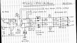
Uploading the As-Built PSU details (Eagle pcb files - which anyone can see if they download the Freeware version of Cadsoft Eagle) for the dual-mono power supply board. Plenty of scope for criticism / improvements and predictions of woe and horror, but it's built, wired up and I ain't changing it now
Note that I've employed some of the advice that Hugh has given out in the past for builders of the original AKSA into the design. He may have updated that advice since those days past but the goal was to capture some of the Classic AKSA approach in this design. Some key quotes from Hugh's advice to builders of AKSA:
"...two independent positive and negative supplies for the two separate amplifier modules. This is electrically the same as monoblock construction"
"We have found that overly large toroidal transformers do not actually improve this amplifier, rather, they appear to slow it down. It is worth noting that all transformers do not sound the same, and a smaller transformer, while conferring slightly less bass control, offers better midrange and top end. We attribute this to the lower charge currents, which produce charge currents in the filter capacitors, particularly with ordinary, regular quality bridge rectifiers. It is evident from our work in this area that switching noise, although at RF frequencies, is somehow perceived by the ear - particularly when the associated hash is eradicated altogether by the use of ultra-fast, soft-recovery diodes."
"Excellent dynamics and realistic, subjective 'slam' from a good solid-state amplifier largely relate to the ability of the power supply to resist voltage sag whilst delivering high, sustained current to a highly reactive load. Voltage ‘sag' is minimised by using a high current transformer with good regulation, quiet rectification, and an adequate, low impedance reservoir capacitor with low self-inductance and thus low ESR at high frequencies."
"10,000uF is the maximum recommended for each rail of a single channel, no more; 4,700uF is adequate."
"A high quality, unregulated system is therefore cheaper and sounds best. We auditioned a good quality series regulated supply, but while it sounded different, it did not necessarily sound superior and was considered unworthy of the extra time and expense. In any event, the performance of the AKSA is so good it rivals most tube systems anyway, and one of the strong drawcards of solid-state is the low cost, low maintenance feature, which a regulated supply partly offsets."
Moving closer to something ready for me to hook up a better source in order to sort out final details of the power amp and do some first listening to the pre.
Uploading the As-Built PSU details (Eagle pcb files - which anyone can see if they download the Freeware version of Cadsoft Eagle) for the dual-mono power supply board. Plenty of scope for criticism / improvements and predictions of woe and horror, but it's built, wired up and I ain't changing it now
Note that I've employed some of the advice that Hugh has given out in the past for builders of the original AKSA into the design. He may have updated that advice since those days past but the goal was to capture some of the Classic AKSA approach in this design. Some key quotes from Hugh's advice to builders of AKSA:
"...two independent positive and negative supplies for the two separate amplifier modules. This is electrically the same as monoblock construction"
"We have found that overly large toroidal transformers do not actually improve this amplifier, rather, they appear to slow it down. It is worth noting that all transformers do not sound the same, and a smaller transformer, while conferring slightly less bass control, offers better midrange and top end. We attribute this to the lower charge currents, which produce charge currents in the filter capacitors, particularly with ordinary, regular quality bridge rectifiers. It is evident from our work in this area that switching noise, although at RF frequencies, is somehow perceived by the ear - particularly when the associated hash is eradicated altogether by the use of ultra-fast, soft-recovery diodes."
"Excellent dynamics and realistic, subjective 'slam' from a good solid-state amplifier largely relate to the ability of the power supply to resist voltage sag whilst delivering high, sustained current to a highly reactive load. Voltage ‘sag' is minimised by using a high current transformer with good regulation, quiet rectification, and an adequate, low impedance reservoir capacitor with low self-inductance and thus low ESR at high frequencies."
"10,000uF is the maximum recommended for each rail of a single channel, no more; 4,700uF is adequate."
"A high quality, unregulated system is therefore cheaper and sounds best. We auditioned a good quality series regulated supply, but while it sounded different, it did not necessarily sound superior and was considered unworthy of the extra time and expense. In any event, the performance of the AKSA is so good it rivals most tube systems anyway, and one of the strong drawcards of solid-state is the low cost, low maintenance feature, which a regulated supply partly offsets."
Attachments
Last edited:
Member
Joined 2009
Paid Member
PowerAmp listening test
I managed to get enough wires in place to power up the power-amps again, no pre-amp in circuit at this point.
Source: iMac through hifmediy U2 Async DAC
Spkr: Audio Nirvana Super 15" full range
I used a Chesky recording of Cristy Baron for most of the listening - female voice and reasonable dynamic range and mix of other sounds.
Note: There was some background buz on power up. Low level and dirty sounding not just hum. It went away when I removed the RCA input jack. It also went away when I left the RCA input cable to the amp but removed it from the DAC - the cable itself is picking up some environmental crap. Note to myself: get a better cable.
Summary:
Both versions of the amp sound good (difference in VAS), plenty of bass, a rich full sound (this speaker tends to bring that out too). The enhanced VAS version was consistently smoother, but not by much. In simulations it has higher OLG and hence a 10dB higher feedback factor over most of the frequency range, even more around 3kHz in the presence region. However, the two amps are close and the enhanced VAS takes away some of the 'air' or 'magic' present in the baseline AKSA design.
In both cases there was something in the treble still (I heard this before in initial listening tests) that I didn't like, some stridency in the lower treble, just a little more 'precise' and cleaner than I remember on my original AKSA 55 clone (which was a lower voltage single output pair version with more distortion).
For the simple VAS (baseline AKSA design) I cycled through some different Cdom values, from 33p to 68p. Whilst this changed the sound from lighter to darker it didn't address the treble issue. It did establish 47p as my preferred value so far (and I was happy with the sound of the ceramic caps compared with a silver mica cap).
I have substituted my TGM7 amp and there is still some lower treble stridency present which is confusing. The only thing constant across all listening sessions so far is use of an Apple product and......... my ears 😱
The TGM7 is my most neutral amp right now, and it sounds a little lifeless compared with the AKSA
Attachments
Last edited:
Member
Joined 2009
Paid Member
Made a few mods to the amps. Standardised on the simple VAS as per the AKSA design. Reduced the idle current through the VAS and the drivers to reduce the temperature of the devices to very warm instead of quite darn hot. Tuned up the bias and dc-offset whilst about it.
The forum seems to like turning my photos sideways without asking me - maybe the mods can fix it.
The forum seems to like turning my photos sideways without asking me - maybe the mods can fix it.
Attachments
Last edited:
Hi Bigun,I managed to get enough wires in place to power up the power-amps again, no pre-amp in circuit at this point.
Source: iMac through hifmediy U2 Async DAC
Spkr: Audio Nirvana Super 15" full range
I used a Chesky recording of Cristy Baron for most of the listening - female voice and reasonable dynamic range and mix of other sounds.
Note: There was some background buz on power up. Low level and dirty sounding not just hum. It went away when I removed the RCA input jack. It also went away when I left the RCA input cable to the amp but removed it from the DAC - the cable itself is picking up some environmental crap. Note to myself: get a better cable.
Summary:
Both versions of the amp sound good (difference in VAS), plenty of bass, a rich full sound (this speaker tends to bring that out too). The enhanced VAS version was consistently smoother, but not by much. In simulations it has higher OLG and hence a 10dB higher feedback factor over most of the frequency range, even more around 3kHz in the presence region. However, the two amps are close and the enhanced VAS takes away some of the 'air' or 'magic' present in the baseline AKSA design.
In both cases there was something in the treble still (I heard this before in initial listening tests) that I didn't like, some stridency in the lower treble, just a little more 'precise' and cleaner than I remember on my original AKSA 55 clone (which was a lower voltage single output pair version with more distortion).
For the simple VAS (baseline AKSA design) I cycled through some different Cdom values, from 33p to 68p. Whilst this changed the sound from lighter to darker it didn't address the treble issue. It did establish 47p as my preferred value so far (and I was happy with the sound of the ceramic caps compared with a silver mica cap).
I have substituted my TGM7 amp and there is still some lower treble stridency present which is confusing. The only thing constant across all listening sessions so far is use of an Apple product and......... my ears 😱
The TGM7 is my most neutral amp right now, and it sounds a little lifeless compared with the AKSA
very nice case and very compact build. Congrats!
reg
Prasi
- Status
- Not open for further replies.
- Home
- Amplifiers
- Solid State
- TGM 1i - an integrated hybrid amp inspired by Hugh Dean