Someone will say, why your THD than NS PDF to write.
I would say.
This is normal and reasonable. Because the actual test is not ideal.
It is capacitor, conductor, and even the influence of the transformer.
In our actual practice, THD will outweigh the value of the PDF.
But 0.002% of LME49810 I think it is normal, and 100% true.
I would say.
This is normal and reasonable. Because the actual test is not ideal.
It is capacitor, conductor, and even the influence of the transformer.
In our actual practice, THD will outweigh the value of the PDF.
But 0.002% of LME49810 I think it is normal, and 100% true.
CLASS A Single-ended Preamp 9
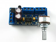
PREAMP 9 before the LJM is a fully vertical design of the first stage of the amplifier. PREAMP 9 is a pure single ended structure, pure class a design.
The so-called single end, is the signal of the entire waveform is to do with one end of the transistor or tube amplifier. Work in a.
Tuning NEVE is a single ended amplifier that has been using discrete components, while other manufacturers use simple Op Amp Circuits.
So the NEVE single ended all discrete circuit has been the representative of analog circuit, with a wider dynamic range than other manufacturers,
One end is the single transistor amplifier due to signal waveform, so the single end circuit without any cross distortion,
This means that the outer signal is also very weak, the signal is usually ignored by people to listen to.
PREAMP 9 has a more warm, sweeter, fuller sound quality than the op amp.
A single ended amplifier circuit amplifier circuit is the oldest original, it has good tone Yun flavor. But the single end circuit is weak to the power supply anti-interference ability,
So the power supply of PREAMP9 is more complicated, and the three stage filtering method is adopted,
The first level uses ONSEMI LM317T production of MOTOROLA as the first level of voltage regulation filter,
The second stage uses a large capacitance inductance and capacitance of the LC filter, coupled with the third transistor RC filter. Power supply as P9 front stage
To provide a very pure, similar to a battery of dc.
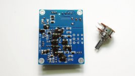
PREAMP 9 uses the original imported C BC547 for the full NPN structure of the pure single ended amplifier circuit, the single end circuit is not complementary to the tube, only PNP without NPN tube. Only the same kind of tube as the amplifier circuit, and the constant current source load.
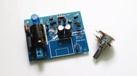
PREAMP9 the design of the whole post piece, because the circuit is more complex, in order to reduce the size of the previous stage. And the patch element has a shorter distance from the line.
This allows the P9 to be installed at the level of a common power amplifier. Directly installed in the power amplifier after the volume control panel on it.
All the products of LJM are mainly through the instrument debugging, different components of the same model, the performance is not the same.
P9 level is mainly in the voice based, on any appearance of landscaping is not.
After class without the use of so-called elements have a fever, what kind of disassemble components.
The front of the P9 ULTRA LOW ESR the main filter capacitor with Panasonic black gold new original FC series capacitor.
Voltage regulator tube using MOTOROLA (M), ONSEMI and other regulators new original.
All transistors are used in the original import of copper pin selected by the test BC547C, all the magnification is about 600.
P9 before the use of a real military manufacturers PCB, the military circuit board is to give the Shenzhou six and other aerospace class suppliers manufacturers.
PREAMP9 before the class will also make the entire audio system to become better, this is the so-called pre - level out of the sound, after the level of output
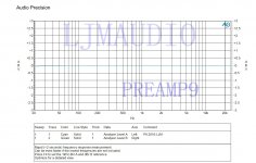
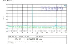
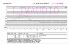
PREAMP9 main parameters are as follows:
THD + N < 0.05%
SNR > 97 DB
Frequency response: 20 hz - 20 KHZ to 0.05 DB
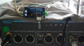
FFT test test platform AP SYS TWO output voltage: 1.06 V
PREAMP 9 before the LJM is a fully vertical design of the first stage of the amplifier. PREAMP 9 is a pure single ended structure, pure class a design.
The so-called single end, is the signal of the entire waveform is to do with one end of the transistor or tube amplifier. Work in a.
Tuning NEVE is a single ended amplifier that has been using discrete components, while other manufacturers use simple Op Amp Circuits.
So the NEVE single ended all discrete circuit has been the representative of analog circuit, with a wider dynamic range than other manufacturers,
One end is the single transistor amplifier due to signal waveform, so the single end circuit without any cross distortion,
This means that the outer signal is also very weak, the signal is usually ignored by people to listen to.
PREAMP 9 has a more warm, sweeter, fuller sound quality than the op amp.
A single ended amplifier circuit amplifier circuit is the oldest original, it has good tone Yun flavor. But the single end circuit is weak to the power supply anti-interference ability,
So the power supply of PREAMP9 is more complicated, and the three stage filtering method is adopted,
The first level uses ONSEMI LM317T production of MOTOROLA as the first level of voltage regulation filter,
The second stage uses a large capacitance inductance and capacitance of the LC filter, coupled with the third transistor RC filter. Power supply as P9 front stage
To provide a very pure, similar to a battery of dc.
PREAMP 9 uses the original imported C BC547 for the full NPN structure of the pure single ended amplifier circuit, the single end circuit is not complementary to the tube, only PNP without NPN tube. Only the same kind of tube as the amplifier circuit, and the constant current source load.
PREAMP9 the design of the whole post piece, because the circuit is more complex, in order to reduce the size of the previous stage. And the patch element has a shorter distance from the line.
This allows the P9 to be installed at the level of a common power amplifier. Directly installed in the power amplifier after the volume control panel on it.
All the products of LJM are mainly through the instrument debugging, different components of the same model, the performance is not the same.
P9 level is mainly in the voice based, on any appearance of landscaping is not.
After class without the use of so-called elements have a fever, what kind of disassemble components.
The front of the P9 ULTRA LOW ESR the main filter capacitor with Panasonic black gold new original FC series capacitor.
Voltage regulator tube using MOTOROLA (M), ONSEMI and other regulators new original.
All transistors are used in the original import of copper pin selected by the test BC547C, all the magnification is about 600.
P9 before the use of a real military manufacturers PCB, the military circuit board is to give the Shenzhou six and other aerospace class suppliers manufacturers.
PREAMP9 before the class will also make the entire audio system to become better, this is the so-called pre - level out of the sound, after the level of output
PREAMP9 main parameters are as follows:
THD + N < 0.05%
SNR > 97 DB
Frequency response: 20 hz - 20 KHZ to 0.05 DB
FFT test test platform AP SYS TWO output voltage: 1.06 V
Attachments
Last edited:
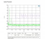
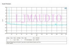
FFT 1K
10K
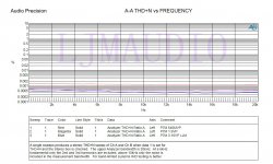
THD+N <0.05%.
PREAMP 9 distortion is not very low.
At least, operational amplifier with lower distortion.
But PREAMP9 has a very good voice,
THD isn't everything. If you need low THD amplifier.
May be more appropriate PREAMP 7 MINI,
7 MINI PREAMP THD + N = 0.0006%.
10K
THD+N <0.05%.
PREAMP 9 distortion is not very low.
At least, operational amplifier with lower distortion.
But PREAMP9 has a very good voice,
THD isn't everything. If you need low THD amplifier.
May be more appropriate PREAMP 7 MINI,
7 MINI PREAMP THD + N = 0.0006%.
Attachments

Is PREAMP 7 MINI an inverting preamplifier ?
Do you clearly state this in specs ?
P7 MINI is op preamp
THD=0.0006%
But in comparison. Listen to a lot of PREAMP 9 better.
Whether it's positive, reverse, enlarge.
Will not be a performance difference between the two.
Most people use is enlarged.
In the practical application of THD is lower, will not be better to listen to.
This only as a reference test.
Attachments
You should publish the schematic so one will know that it is INVERTING amp.
I am not introduce PREAMP 7 MINI here.
PREAMP 9 NO INVERTING 。
😀
PREAMP 9 GAIN VOLTAGE= 11
POWER AC 24-28V ONE。
IC= 25 MA
Output impedance 20K 。
Recommend collocation L series amplifier.
L20SE L20V7, L20, L6 to use.
Because of the output capacitor.
Suggest to cancel the L series input capacitance is used.
Do not recommend collocation not LJM design amplifier after use. The unintended problems may occur.
Last edited:
Hello,
Just ordered two L15D boards and awaiting for delivery. In the meantime looking for good SMPS, but don't know if I can use one for both boards or not. For simplicity and price I prefer one, but not sure if I can.
Just ordered two L15D boards and awaiting for delivery. In the meantime looking for good SMPS, but don't know if I can use one for both boards or not. For simplicity and price I prefer one, but not sure if I can.
Hello Ljm_Ljm
I have your L20 and L15D amplifiers. I love them, thank you! Is the Preamp 9 good to connect to the L20 and L15D amplifiers?
I have your L20 and L15D amplifiers. I love them, thank you! Is the Preamp 9 good to connect to the L20 and L15D amplifiers?
Where can they be ordered and how much USD?
Most of his designs are available on eBay.
Preamp 9 Single Ended Pure Class A 20Hz 20kHz Transistor Preamplifier Board | eBay
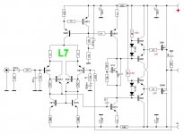
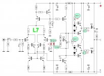
I restored scheme L7.
Please report errors...
BR
Thank you for doing this. I'm not sure which board this reflects, presumably one you bought. Please specify your source example. I think the feedback divider should be 1K, not 10K.
Changes? I would bootstrap both of the gate driver buffers, in opposite directions and using higher currents. There is risk of crossover distortion as it is, and you don't get much high side drive.
Thanks again for reverse engineering it. Might be fun to build and tweak.
Attachments
L7 Schematic in Eagle
Here is an Eagle format schematic of the L7 board. I changed two resistor values which seemed off by orders of magnitude. I changed the 1815 transistors to 5551 for ease of stocking. There are other changes I might suggest, but this reflects the board as built. Enjoy.
Here is an Eagle format schematic of the L7 board. I changed two resistor values which seemed off by orders of magnitude. I changed the 1815 transistors to 5551 for ease of stocking. There are other changes I might suggest, but this reflects the board as built. Enjoy.
Attachments
Regarding my post of the L7 schematic, be aware the 1815 transistors are ECB pinout, not the typical EBC. I made the change for my convenience in stocking, and I don't mind bending leads to fit, but these are not drop in replacements. For simulation it won't matter, but for assembly using the stock board, beware of the difference.
- Home
- Vendor's Bazaar
- LJM Audio