Fluke is the best DMM you can get. "The quality remains even after the price is forgotten". I have been using an old 99 for 15 years, it is starting to fade in the screen, but it is exceptional and unburstable.......
Some of the digital CROs are getting cheap. Might ditch my 475 Tek this year.........
Good choice, X!!
Hugh
Some of the digital CROs are getting cheap. Might ditch my 475 Tek this year.........
Good choice, X!!
Hugh
Hi Hugh,
Yes, I love my Fluke - even how the selector knob feels buttery smooth when you rotate it makes a difference. Glad I got it because I use it all the time. I miss my old Tek TDS220 - simple and worked well.
I left the amp on several hours now - not running warm and bias still stable at set point of 160mA. The frequency function of the Fluke says 67kHz. But who knows what the amplitude is. Listening to it sounds fine still. I guess I won't know unless Terry tries 10R gate stoppers and looks at it on a scope. Don't forget to add 2k2 on input.
I don't have a scope but bias is stable. Sound is clean - I can take a speaker distortion scan and see if any oscillation as that shows up as increased distortion. I think that 2k2 and 330pF form. 200kHz low pass filter as Andrew T says and this fixed a lot of the problems of RF getting in and causing problems. Perhaps you can try the 2k2 mod and 10R stoppers on yours since you have a scope?
I'm wondering how you can state this, " The slope of the rising/falling edge gets progressively steeper with lower value" if you don't have a scope.
Be careful making statements that you have not proved. Others will come here from using the search feature and think your statement is true. My amp was not stable at all using the 4R7 stoppers. Because yours hasn't blown up is not proof that it is a good practice. Mine wouldn't work with the input shorted so RF was not the issue. I have searched through all of the amps I've built with hexfet outputs and the lowest stoppers I could find were on the SKA GB150 and those were 47R. Most all of the other were at least 100R and a couple were 1k. I see 220R a lot. Where did you get the idea that 10R is better?
Terry, I should have prefaced with "based on the simulations," the slope of the square wave edges got steeper as I changed the resistance. I wanted to go 0R but the shape of the square wave was best with 4.7R. I agree we see 220R all over the place. Same as 100nF bypass caps. A lot of it is usual standard practice. I tried 220R initially but noticed the corners on the simulated square wave got tighter and sharper with smaller resistances.
Have you tried adding the 2k2? It makes a difference.
So in short, there is some basis for what I am doing and it's not simply pulling stuff out of thin air. 🙂
The amp was simulated before being built. Sim did not catch fact I was missing the resistor for the 330pF RF filter because Spice world is devoid of RF noise from cell phones and DACS etc. but it got the amp pretty close to final form.
Last edited:
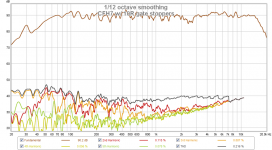
Measurement with speaker shows that this amp with 10R gate stopper is still one of the cleanest amps in my stable of amps. Nothing unusual HD wise here. A very clean performance.
Here is measured harmonic distortion of my SS 10F/8424 and RS225-8 transient perfect speakers:

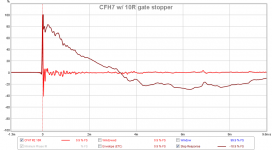
Here is measured impulse and step response:

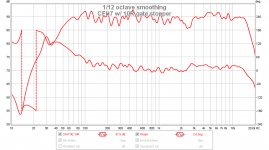
Here is measured frequency response and phase:

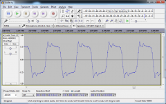
Here is a record of a 2kHz square wave played on the speaker - it resembles the step response:

Here is measured harmonic distortion of my SS 10F/8424 and RS225-8 transient perfect speakers:
Here is measured impulse and step response:
Here is measured frequency response and phase:
Here is a record of a 2kHz square wave played on the speaker - it resembles the step response:
Attachments
Last edited:
You've copied VSSA schematic, what did you expect, to get crap?
There are thousands VSSA users worldwide, you could just say thank you for instance.
And finally, buy yourself proper oscilloscope and get some basic training about electronics.
There are thousands VSSA users worldwide, you could just say thank you for instance.
And finally, buy yourself proper oscilloscope and get some basic training about electronics.
You've copied VSSA schematic, what did you expect, to get crap?
There are thousands VSSA users worldwide, you could just say thank you for instance.
And finally, buy yourself proper oscilloscope and get some basic training about electronics.
Lazy Cat,
I am not sure what you are so up in arms about. I have acknowledged in post #1 that this was inspired by the VSSA project (Jason K variant) I did last. Furthermore, you did not invent this so please don't get upset every time someone uses a variant of this topology without showing their deep unending gratitude to you for your VSSA. If it has been around for 40 years and Garborbela posted it on DIYA years before you did, so by definition, you did not invent it. So please stop harassing me, and othersfor not thanking you for your invention ad naseum.
And the comment about getting basic training on electronics is uncalled for. I agree I need an oscilloscope, and have already said thus.
If you have nothing but gripes and snipes to post, just stop trolling around here. We don't need it.
. . . With an attitude like that, you can understand why Lazy Cat is on my ignore list.
Last edited:
Lazy Cat,
I am not sure what you are so up in arms about. I have acknowledged in post #1 that this was inspired by the VSSA project (Jason K variant) I did last. Furthermore, you did not invent this so please don't get upset every time someone uses a variant of this topology without showing their deep unending gratitude to you for your VSSA. If it has been around for 40 years and Garborbela posted it on DIYA years before you did, so by definition, you did not invent it. So please stop harassing me, and othersfor not thanking you for your invention ad naseum.
And the comment about getting basic training on electronics is uncalled for. I agree I need an oscilloscope, and have already said thus.
If you have nothing but gripes and snipes to post, just stop trolling around here. We don't need it.
he should apply for a copyright for his design, like ESP or AKSA which are copyright material. So that it might be easier for moderators to remove copies like yours... Just a suggestion. Nothing else.😀.
I didn't know the meaning of troll, I looked up the dictionary, now I understand perfectly.
Last edited:
Copyright isn't meant to protect designs from people doing DIY or not for profit efforts. Copyright is for artistic content like writing, visual art, music. Patents are for technical devices and processes. This isn't patentable as it has been invented already and probably has been in public domain for sometime now. Even patented stuff isn't protected from DIY efforts - just look at all the Synergy horns and tapped horn designs that Danley has patents on. Those are all hot topics of DIY development and builds on this forum. Patents protect from commercial use of an idea.
Sometimes in life you come across unsavory individuals.
I would simply put him on your ignore list.
I would simply put him on your ignore list.
I have left it on all day and with music playing and no fan, heatsink is warm but not too hot (can hold it for about 10 seconds). Bias remeasured and is stable at about 160 to 170mA. DC offset remeasured to be 1mV on one and 5mV on the second.
Last edited:
Hello 🙂
Have the amp been measured in 4 ohm, and how did it perform ? And can it drive a 4 ohm load ? 🙂
Is it possible to get a small review from those who has build it ? And compared to what? 🙂
Is it possible what someone has a spare set of PCB's ? 😀😀
Have the amp been measured in 4 ohm, and how did it perform ? And can it drive a 4 ohm load ? 🙂
Is it possible to get a small review from those who has build it ? And compared to what? 🙂
Is it possible what someone has a spare set of PCB's ? 😀😀
IRFP240/9240 should be able to drive 4ohm loads no problem with 35v rails. I have not tested it yet but the outputs are bullet-proof as long as you keep it within SOA. At 53v rail it can run 120w into 8ohms no problem.
If you want a review (complete with sound clips and compared to 9 other amps), check out this thread:
http://www.diyaudio.com/forums/soli...y-simple-quasi-mosfet-amp-14.html#post4811896
You have PM if interested in PCB's.
If you want a review (complete with sound clips and compared to 9 other amps), check out this thread:
http://www.diyaudio.com/forums/soli...y-simple-quasi-mosfet-amp-14.html#post4811896
Is it possible what someone has a spare set of PCB's ?
You have PM if interested in PCB's.
Last edited:
I'm doing a philosophically similar design on Eagle, and I need a library with the better transistors. In my library searches so far, I have not found power parts in TO-247 package, but I used something I think is a similar lead spacing and edited the values so the schematic fakes it, and I can lay it out. Pretty hit and miss. I'm trying to do an amp with 4 actives, knowing it will sound awful but the goal is low active count, half decent sound and no fire.
So, are there parts libraries people use? Steep learning curve here.
Also to share the design, how do people post these things, PDFs, jpegs, ??? I have not figured how to export schematics and boards from Eagle. I could print the schematic, scan it and show a JPEG, how lame is that? There has to be an efficient way.
I know you geniuses have this down, share the knowledge.
Steep learning curve here.
Yeah, if you're using Eagle that would be an understatement. After playing around with it for a couple of hours, I decided it wasn't for me...free or not.
To upload a JPEG, click on the paper clip near the top of the grey box. Then a Manage Attachments box will pop up. Browse for the photo or files you want to upload and click upload in the bottom right corner.
Most people post Gerber files for PCB designs by placing them in a zip folder and then attaching the folder the same way by clicking on the paper clip icon.
Some folks etch their own boards by using some PDF image. I don't know how all that works since I have all my boards professionally made.
Hope that helps.
A lot of people who do excellent layouts in this forum use Sprint. It makes nice looking layouts but is not free. It also doesn't error check the schematic like Eagle. People also post Sprint files. I like PNG format images - they seem to work reliably in most browsers and operating systems.
There are some excellent sounding 4 transistor amps actually. Pass ACA class A is one.
There are some excellent sounding 4 transistor amps actually. Pass ACA class A is one.
Just to inform all of you, VSSA (Very Simple Symmetrical Amplifier) is my amp and it was sold in hundreds few years ago. Its successor is First One S which will be released this year. More in below VSSA link.
BTW Gaborbela is not electronic guy, he took sch from god knows where, so to be correct the original author of this topology is unknown.
I came to VSSA sch from my SSA and TSSA schematics from naturally developing the concept and did not know anything about the guy and his drawings. Just to be clear.
Just a little correction, I know where the orig. schematics comes from.
The one posted at the first post was simplified (or modified) by me 2 decades a go, actually that was drawn by me! 🙂
I built different variant of these amp (some other DIT-ers to) over the years just to clear.
The last variation with different semiconductors and some tweak was far the best sounding amp I ever built..
Yes it had some thermal drift issue...
Will be back to these project before the end of these year.. I was unable to deal with because of my health issue but thank God getting better day by day..
I do not claim I am a top electronic guy or a guru but I learned a few thinks over the years....😀😀 thanks to all...
I think we hear to learn from each other at least some of us.
I do want to follow the thread....and I am happy if people benefit from my posts.🙂
Greetings
I'm doing a philosophically similar design on Eagle, and I need a library with the better transistors. In my library searches so far, I have not found power parts in TO-247 package, but I used something I think is a similar lead spacing and edited the values so the schematic fakes it, and I can lay it out. Pretty hit and miss. I'm trying to do an amp with 4 actives, knowing it will sound awful but the goal is low active count, half decent sound and no fire.
So, are there parts libraries people use? Steep learning curve here.
Also to share the design, how do people post these things, PDFs, jpegs, ??? I have not figured how to export schematics and boards from Eagle. I could print the schematic, scan it and show a JPEG, how lame is that? There has to be an efficient way.
I know you geniuses have this down, share the knowledge.
I have been using eagle, steep learning curve for sure. But once you get the hang of it (after many many hours), you will come to like its schematic checking feature.
i have attached IR mosfet library , see if you can import into your library and use it.
From the eagle board/schematic 'file' menu, goto export/image , give a file name/ resolution and press ok. an image of the current active layers will be created in the same path as that of your brd file.
There is series of videos on youtube, that should help a bit. https://youtu.be/ge3NZM7_F9w
Attachments
Last edited:
- Home
- Amplifiers
- Solid State
- CFH7 Amp