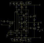
Hi X glad you found the mistake and that board working. Here are the latest layout evolution including the Rin (2k2 juste afyer 10uf input cap).
Attachments
Last edited:
Resistor will not change the bias spreader tempco, better use a LED, I think red one could be good.
By the way Ivo, why do you think IRFP340/9240 are beter complements then IRFP240/9240, I don't see it from the datasheets. Forward transconductances are even further apart.
Damir
Exactly. The additional voltage drop element has to be a "voltage reference" one, having the constant voltage drop regardless of the current flow (within the reasonable limits).
The red LED is a tested solution for IRFP240/9240 biasing - I have used it in a number of HexFET-based designs with very good result.
Hi Valery,
What other changes need to be made to insert the LED ? I added it to my spice file and the bias got weird.
Hi X glad you found the mistake and that board working. Here are the latest layout evolution including the Rin (2k2 juste afyer 10uf input cap).
Why are you using a lifted ground? The input ground is not separated so you are lifting to whole thing.
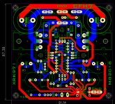
Closeup with correct parts
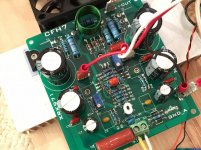
Here is my amp with all correct resistors (no paralleled or series combos), NP0 ceramic caps for the 10pF, and the 2k2 input resistor on the bottom (not shown). The bias is stable now with the 2k2 in place. Before, it would sometimes drift (probably due to oscillation). Do I really need the LED in the bias spreader if it seems to be working fine? What performance improvement should I expect with the LED in place?

Here is my amp with all correct resistors (no paralleled or series combos), NP0 ceramic caps for the 10pF, and the 2k2 input resistor on the bottom (not shown). The bias is stable now with the 2k2 in place. Before, it would sometimes drift (probably due to oscillation). Do I really need the LED in the bias spreader if it seems to be working fine? What performance improvement should I expect with the LED in place?
Attachments
Here is my amp with all correct resistors (no paralleled or series combos), NP0 ceramic caps for the 10pF, and the 2k2 input resistor on the bottom (not shown). The bias is stable now with the 2k2 in place. Before, it would sometimes drift (probably due to oscillation). Do I really need the LED in the bias spreader if it seems to be working fine? What performance improvement should I expect with the LED in place?
Hi X,
The aim of the LED is to reduce the "sensitivity" of the thermal feedback, making it more suitable for tempco of particular output devices. You may notice certain over-regulation as is - e.g. the bias goes up after power-on, and then goes pretty much down as soon as the heatsinks get warm.
Terry - you need to adjust (increase) the resistor in series with the trimmer after adding the LED, in order to bring the bias range back to the one you've had before.
This amp does vary greatly with temperature. Starts low and goes up a lot as it warms up. Then after playing music for a while it drops a bunch. It would be worth trying the LED, Easy enough to cut in on my home etched boards.
Let me know what resistor values you arrive at for the LED version. You have to use the Vbe multiplier equation otherwise it won't work. I know it's real finicky and that 6.8k/1k pot/220R was worked out by me when I made the FH9. changing any of those values and it no longer works.
Would you please share the latest Gerbers. Thank you very much for your contribution!Hi X glad you found the mistake and that board working. Here are the latest layout evolution including the Rin (2k2 juste afyer 10uf input cap).
Would you please share the latest Gerbers. Thank you very much for your contribution!
Here they are but take a look at job before, there shouldn't be a issue...first version was Ok for X.
Marc
Attachments
After fixing my bad resistor value, and adding 2k2 resistor on input, the Idefixes version 1 works great. It has the advantage of an onboard inductor. I wonder if it's worth waiting for the LED mod for the bias spreader.
Listening to it now. I have to say it has the most powerful and articulate bass of any of my amps (subjectively).
I may try the 4.7R or 10R gate stopper resistors now that there is good RF filtering on input. The slew rate should improve with lower resistance here
Listening to it now. I have to say it has the most powerful and articulate bass of any of my amps (subjectively).
I may try the 4.7R or 10R gate stopper resistors now that there is good RF filtering on input. The slew rate should improve with lower resistance here
After fixing my bad resistor value, and adding 2k2 resistor on input, the Idefixes version 1 works great. It has the advantage of an onboard inductor. I wonder if it's worth waiting for the LED mod for the bias spreader.
Listening to it now. I have to say it has the most powerful and articulate bass of any of my amps (subjectively).
I may try the 4.7R or 10R gate stopper resistors now that there is good RF filtering on input. The slew rate should improve with lower resistance here
As AndrewT explain it, it's not important to have it on board....i love the possibility in layout that offert exporting inductor out board as Output devices completly under board, size bord reducing...
Marc
Ok, it's confirmed that this board works with 10R gate stopper resistors, The slope of the rising/falling edge gets progressively steeper with lower value. It seems the 2k2 on the input is keeping everything stable.
Sounds very nice - I have to find some drum solos to listen.
Sounds very nice - I have to find some drum solos to listen.
Ok, it's confirmed that this board works with 10R gate stopper resistors, The slope of the rising/falling edge gets progressively steeper with lower value. It seems the 2k2 on the input is keeping everything stable.
Sounds very nice - I have to find some drum solos to listen.
Have you attached it to a scope? Lets see the pics.
I don't have a scope but bias is stable. Sound is clean - I can take a speaker distortion scan and see if any oscillation as that shows up as increased distortion. I think that 2k2 and 330pF form. 200kHz low pass filter as Andrew T says and this fixed a lot of the problems of RF getting in and causing problems. Perhaps you can try the 2k2 mod and 10R stoppers on yours since you have a scope?
Last edited:
I think I experienced them when I did not have the 2k2 and the bias kept rising until it hit 1200mA. Let's see what happens and hopefully it doesn't burn out. I need an O scope. 🙂
Last edited:
Oscilloscope and DMM is the main tool for audio DIY.
Stay up the good work .
Thiago
My Fluke DMM has a frequency meter function. Maybe it can "hear" inaudible oscillations?
My Fluke DMM has a frequency meter function. Maybe it can "hear" inaudible oscillations?
OMG

- Home
- Amplifiers
- Solid State
- CFH7 Amp