Is not the speaker impedance you must be concerned with, is the board max voltage. While the IC supports a little more, most boards came with 25V capacitors, so keep it at, or slightly under, that (I would use 24V).
The step up converter is ok.
Thanks jopereira! 🙂
I would not go above 22-23V with questionable capacitors inside. I popped a cheapo cap 25V@24V, and it gave an insane amount of smoke with a bang. You do not want that to happen inside your car..
Also make sure that the ground wire for the amp is connected to the same point/wire as your source/car deck. Earlier I recommended the tpa3116 to buddies for car use but not anymore. Its just to much hassle dealing with ground loop noise. Finding a cheap fully isolated step up psu is like winning the lottery^^.
Also make sure that the ground wire for the amp is connected to the same point/wire as your source/car deck. Earlier I recommended the tpa3116 to buddies for car use but not anymore. Its just to much hassle dealing with ground loop noise. Finding a cheap fully isolated step up psu is like winning the lottery^^.
Last edited:
I would not go above 22-23V with questionable capacitors inside. I popped a cheapo cap 25V@24V, and it gave an insane amount of smoke with a bang.
I guess that cap would blow @12v anyway 🙂
Mono TPA3116 boards.
There seem to be a few around. Though not a lot of discussion about them..... That I can find by search on the forums anyway. 🙂
There are also Breeze and Sure, YJ(?) boards out there.
XH-M544
92x58x16mm
HCH-1618BTL
50x38mm!
XH-M542
79x54x16mm.
One I have seen on here but no board ID
75x50mm
DPA501-24
52x48x18
If there's been any in-depth discussion of these, I'd be interested in knowing.
HCH-1618BTL looks nice. Thru hole capacitors. Easy to exchange. Very simple board.
The XH-M542 you can also find as a Sanwu board. Have not tried it. But I do not like that they used an opamp.
I tried the no board ID one. To high gain, and configured as slave for some reason. Very nice rubycon capacitor, though it is SMD mounted. Also, "only" 25V rating. Pretty low for a 24V D-amp.
Ended up using the blue Sanwu TPA3118 mono boards.
Hi, today I’ve got my first TPA3116 board, the dual chip XH-M190 v.3; it was configured in the master/slave mode, with 26 dB gain for each channel.
The SYNC pins of the two chips were connected via a R-C with the wrong values (10 Kohm and, I suppose, 1 nF) so the sync signal at the slave side was near to zero.
The master chip was switching at a frequency of about 400 KHz and the slave frequency was just above 100KHz, so the two was not synchronized.
I’ve got synchronization (both the chips at 400KHz) simply removing the 1nF capacitor (C41 in TI datasheet, fig. 37), and leaving the resistor at 10 Kohm.
(note that removing a component is easier than replace two SMD components).
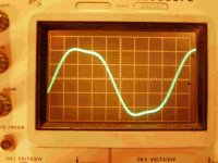
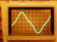
Then I started to test the two channels of the board, using a sine wave generator and an oscilloscope, connecting the probe between ground and one of the BTL output.
The slave channel was regular, but the master was not, showing a strong distortion when the signal frequency was between 9 and 12 KHz (see the attached pictures, showing the two BTL outputs); outside this frequency interval the waveform was good; power supply was 20V, load was 8 ohm for each channel, output power was about 10 W.
Moreover, the master channel frequency response showed a peak of about 8-9 dB at 33KHz, that is the resonant frequency of the output filter (33uH and 0.68uF); the peak of the slave channel, approximately at the same frequency, was much smaller (1-2 dB).
Can anybody explain this behavior?
The SYNC pins of the two chips were connected via a R-C with the wrong values (10 Kohm and, I suppose, 1 nF) so the sync signal at the slave side was near to zero.
The master chip was switching at a frequency of about 400 KHz and the slave frequency was just above 100KHz, so the two was not synchronized.
I’ve got synchronization (both the chips at 400KHz) simply removing the 1nF capacitor (C41 in TI datasheet, fig. 37), and leaving the resistor at 10 Kohm.
(note that removing a component is easier than replace two SMD components).
Then I started to test the two channels of the board, using a sine wave generator and an oscilloscope, connecting the probe between ground and one of the BTL output.
The slave channel was regular, but the master was not, showing a strong distortion when the signal frequency was between 9 and 12 KHz (see the attached pictures, showing the two BTL outputs); outside this frequency interval the waveform was good; power supply was 20V, load was 8 ohm for each channel, output power was about 10 W.
Moreover, the master channel frequency response showed a peak of about 8-9 dB at 33KHz, that is the resonant frequency of the output filter (33uH and 0.68uF); the peak of the slave channel, approximately at the same frequency, was much smaller (1-2 dB).
Can anybody explain this behavior?
Attachments
Last edited:
I don't know what's going on, but I doubt connecting scope ground to one of the outputs is the right way to go. Connect it to power ground, probe one of the outputs.
I don't know what's going on, but I doubt connecting scope ground to one of the outputs is the right way to go. Connect it to power ground, probe one of the outputs.
It's what I've done; the two pictures are the voltage of each output referred to ground.
The voltage across the load is the difference between these voltages; I wonder if this difference could be a sine wave; later I'll try with two probes and using CH1-CH2 on the scope.
Last edited:
Fulvio, I think I used the same board as you. I'm keen to know how I can improve this board. Can you tell me how it affects the sound to have one board in master mode and the other in slave? Also, which 1nF to remove? If you have some pics I'd be most thankful.
I just put it in an enclosure this past weekend:
With my test speakers, which are small watt sensitive speakers, the hiss is audible. But with my bookshelf which is not that sensitive, it's silent.
I just put it in an enclosure this past weekend:
An externally hosted image should be here but it was not working when we last tested it.
With my test speakers, which are small watt sensitive speakers, the hiss is audible. But with my bookshelf which is not that sensitive, it's silent.
Fulvio, I think I used the same board as you. I'm keen to know how I can improve this board. Can you tell me how it affects the sound to have one board in master mode and the other in slave? Also, which 1nF to remove? If you have some pics I'd be most thankful.
According to TI, the best configuration is one chip master and the other chip slave; in this way, the two chip are synchronized, that is, they work at exactly the same switching frequency; if they work as master/master, they are independent, so the switching frequencies (nominal 400KHz) can be slightly different; expecially if you use a single power supply, spurious audible tones (at a frequency equal to the difference of the two switching frequency) can be generated and produce noise at the output.
First of all, read and post the value of the following resistors:
R3, R4, R9, R10 and R13 (if present);
They are all between the four electrolytic capacitors and the heatsink.
These values define the working mode (master/slave) of each chip and also the gain of each channel (left/right).
Concerning the improvement to the board, you can read post #9257 in this thread.
Moreover, in order to improve the thermal exchange and prevent overtemperature of the chips, put some thermal compound between the power metallic pad of each chip and the heatsink (my board has no trace of thermal compound).
Hi fulvio, the values are:
R3=100k
R4=20k
R9=47k
R10=75k
R13=10k
I understand they make a 26dB gain? Does it sound a lot different if we make it 20dB gain? And with lower gain does that make the output lower? Thanks.
R3=100k
R4=20k
R9=47k
R10=75k
R13=10k
I understand they make a 26dB gain? Does it sound a lot different if we make it 20dB gain? And with lower gain does that make the output lower? Thanks.
Hi fulvio, the values are:
R3=100k
R4=20k
R9=47k
R10=75k
R13=10k
I understand they make a 26dB gain? Does it sound a lot different if we make it 20dB gain? And with lower gain does that make the output lower? Thanks.
Exactly like mine; one chip is set as master and the other as slave; but to get the slave synchronized with the master, a clock signal has to be transmitted to the slave and this is made through R13 and C33.
Unfortunately, the values of these components (10K and 1nF) are wrong, so the slave doesn't receive a valid synchronization signal and works completely out of specification (switching frequency of about 100KHz), with a very high ripple at the output.
As stated by TI, the correct values should be R13= 4.7K and C33= 47pF, but in my board I got synchronization simply removing C33 and leaving R13 at 10K (a very simple operation).
I really don't know if synchronization can improve the audio quality, but for sure one chip of your board is working now in a non-standard mode and the output filter is suffering for this.
Concerning the gain, I should not modify it.
TPA310 1x30W Amp
Hi,
Does anyone have any experience with Sure's TPA3110 1x30W mono amps? A link to Sure's site is given below:
Sure Electronics' webstore 1 x 30 Watt Class D Audio Amplifier Board - TPA3110
What I actually want to do is use two of these as monoblocks to power a pair of FE126EN speakers. Would replacing the power caps be a good idea? I know that on the TPA3110 2x8W board, many suggesting replacing the caps with Panasonic or Elna 470uF/25V caps.
Any suggestion, including other mods would be greatly appreciated.
Thanks,
Kingshuk
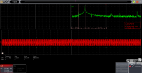
Attachments
I had the opportunity to do a FFT on my sub channel and, while not audible in my subwoofer, there was a lot of noise past the audible frequencies.Exactly like mine; one chip is set as master and the other as slave; but to get the slave synchronized with the master, a clock signal has to be transmitted to the slave and this is made through R13 and C33.
Unfortunately, the values of these components (10K and 1nF) are wrong, so the slave doesn't receive a valid synchronization signal and works completely out of specification (switching frequency of about 100KHz), with a very high ripple at the output.
As stated by TI, the correct values should be R13= 4.7K and C33= 47pF, but in my board I got synchronization simply removing C33 and leaving R13 at 10K (a very simple operation).
I really don't know if synchronization can improve the audio quality, but for sure one chip of your board is working now in a non-standard mode and the output filter is suffering for this.
Concerning the gain, I should not modify it.
On stereo channels, a " gremlins" noise was present an audible (like digital communications noise).
Solved with a jump on my 10K resistor (I don't think I have a capacitor there).
Solved with a jump on my 10K resistor (I don't think I have a capacitor there).
I correct myself... I do have a capacitor, thought I don't know the real value.
Attachments
Hi,
Does anyone have any experience with Sure's TPA3110 1x30W mono amps? A link to Sure's site is given below:
Sure Electronics' webstore 1 x 30 Watt Class D Audio Amplifier Board - TPA3110
What I actually want to do is use two of these as monoblocks to power a pair of FE126EN speakers. Would replacing the power caps be a good idea? I know that on the TPA3110 2x8W board, many suggesting replacing the caps with Panasonic or Elna 470uF/25V caps.
Any suggestion, including other mods would be greatly appreciated.
Thanks,
Kingshuk
My Sure TPA3110 stereo has plenty of power for my FE126En Frugal Horn Mk3's. I can tell little difference between it and the TPA3116 power wise.
Here are some images (before/after).
BTW, 10K+1nF is what datasheet says.
The values in datasheet are wrong; look at the TI answer in post 3440 of this thread.
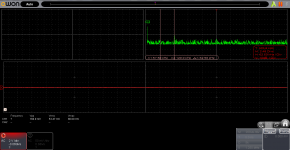
In the first picture you posted, I can see a strong line at 116KHz that should be the switching frequency of the slave not synchronized; after modification, I should expect this line move to 400 KHz, but I can't see it; maybe it is under the noise floor, thanks to the greater attenuation of the output filter at 400 KHz.
Since you are able to perform FFT analysis, did you ever try to measure distorsion of the output signal?
I'm trying to do this using an old analogic selective voltmeter, but first results are showing a distortion higher than 1% , at 10W output power.
If somebody is interested, I can post the results of the measure.
Thank you, I'm planning to remove C33 and do the bootstrap mod. 😀😀As stated by TI, the correct values should be R13= 4.7K and C33= 47pF, but in my board I got synchronization simply removing C33 and leaving R13 at 10K (a very simple operation).
I really don't know if synchronization can improve the audio quality, but for sure one chip of your board is working now in a non-standard mode and the output filter is suffering for this.
Concerning the gain, I should not modify it.
The values in datasheet are wrong; look at the TI answer in post 3440 of this thread.
In the first picture you posted, I can see a strong line at 116KHz that should be the switching frequency of the slave not synchronized; after modification, I should expect this line move to 400 KHz, but I can't see it; maybe it is under the noise floor, thanks to the greater attenuation of the output filter at 400 KHz.
Since you are able to perform FFT analysis, did you ever try to measure distorsion of the output signal?
I'm trying to do this using an old analogic selective voltmeter, but first results are showing a distortion higher than 1% , at 10W output power.
If somebody is interested, I can post the results of the measure.
Yes, the filter does a great job (@400KHz, not tuned to 100KHz...).
In another TDA3116 stereo amp I have, the 400KHz line is much more visible.
No, I haven't tried to measure distortion.
I saw these videos and find them very useful in that. Here is audible the noise produced by different working frequencies of the two IC:
https://youtu.be/5vNXid174fs
https://youtu.be/JoFLhU_cX54
- Home
- Amplifiers
- Class D
- TPA3116D2 Amp