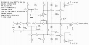
This is the schematic diagram,not the layout🙂Attaching it again....
Attaching it again....
This is the schematic diagram. What we normally call the layout - is PCB layout.
That only means there is some issue with either your signal source, or your power amp. This one does not influence the sound by design - at least in the setup, where you're trying to use it.
Good advice from John, fully agree with Ammel.
X, when will you arrange something to measure the amps (not only the speakers)? 😉 The distortion level of the circuit, like the Apex's one, is too low to see in the end of the whole circle, including the speaker, microphone, etc. 😛
I need to stop being a "greedy boyz" as the Pass forum guys would say and invest in a high quality sound card with high SNR and ultra low distortion as the basis of my amp measurement rig. All I can do now is check to make sure the amp/preamp doesn't change what is audible. It's a sanity check sort of and has uncovered stuff like the M2's high levels of distortion which indeed show up at the mic. But stuff like a clean preamp that is less than speaker HD of -55dB is not going to show anything beyond speaker's native HD spectrum. I am glad I proved to myself that symmetric LTP input and complementary output gives nice preamp. Could be basis of a good MOSFET amp probably by placing hexFETs at outputs for 8 transistor amp. Replacing the BC550/560 outputs here with heatsinked BD139/140's might make a decent headphone amp.
I am looking at the Scarlett series of external USB sound cards for an amp measuring rig.
Last edited:
I need to stop being a "greedy boyz" as the Pass forum guys would say and invest in a high quality sound card with high SNR and ultra low distortion as the basis of my amp measurement rig. All I can do now is check to make sure the amp/preamp doesn't change what is audible. It's a sanity check sort of and has uncovered stuff like the M2's high levels of distortion which indeed show up at the mic. But stuff like a clean preamp that is less than speaker HD of -55dB is not going to show anything beyond speaker's native HD spectrum. I am glad I proved to myself that symmetric LTP input and complementary output gives nice preamp. Could be basis of a good MOSFET amp probably by placing hexFETs at outputs for 8 transistor amp. Replacing the BC550/560 outputs here with heatsinked BD139/140's might make a decent headphone amp.
I am looking at the Scarlett series of external USB sound cards for an amp measuring rig.
Scarlett looks good

The NE5532, used properly, is essentially perfect. The remaining imperfections (distortion, noise, etc) are so low that they cannot be detected by human hearing.I already tried using the ne5532 . The sound was muffled and seemed like too much gain was overloading the amp.
So, either there was a problem with your circuit or your implementation of it, or you were hearing a muffled sound from somewhere else in the audio chain. Most likely the speaker, second most likely, the audio source itself.
If you used the resistance values in the schematic you showed, there is only +6 dB of gain. If you run it off +/- 15V supply rails, it will be able to accept up to at least 12 volts, peak to peak, of input, without clipping.
If +6dB was actually too much gain and was distorting your power amp, then you don't need a preamp at all!
I very much recommend figuring out what was wrong with your 5532 build, and fixing it. That is much better than building far more complex discrete transistor circuits, that actually have far worse performance. John Curl is quite right, some of the discrete circuits in this thread date back to the 1960's.
-Gnobuddy
Perhaps I'm missing something, but it doesn't look as though there is much open-loop voltage gain, either.I built one channel of the Apex BJT preamp. 6 transistors and miscellaneous parts make it just as complicated to build as a full blown power amp.
Without lots of open-loop gain, negative feedback can't adequately remove the various nasties that come with transistor non-linearity.
-Gnobuddy
Perhaps I'm missing something, but it doesn't look as though there is much open-loop voltage gain, either.
Without lots of open-loop gain, negative feedback can't adequately remove the various nasties that come with transistor non-linearity.
-Gnobuddy
These transistors have Hfe in the 470 range. Isn't open loop gain on two stages 220k?

P16:
Another BC550/560 LTP implementation. Probably a nice headphone amp even. Do you have PCB files for layout or Gerbers?
Another BC550/560 LTP implementation. Probably a nice headphone amp even. Do you have PCB files for layout or Gerbers?
Yes, I prepare the archive and I join as soon as possible.P16:
Another BC550/560 LTP implementation. Probably a nice headphone amp even. Do you have PCB files for layout or Gerbers?
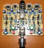
SR PP12 Pcb by alexmm.
Cam you please post the pcb layout. Thanks...
The 5532 is OK, not great, but if you are having a problem, I would look at the power supply bypasses that should be close to the op amp, and the kind and quality of the input cap (no ceramics).
The 5532 is OK, not great,
So which dual op-amp do you consider to sound great?
Not defending the '5532, just curious what you like?
I prefer fet input, slightly higher slew rate op amps like the OPA2134 in this application. About the same noise, RF resistant, somewhat faster, low DC offset, reasonable price, and sounds OK. I'm sure there are others that might be better in specific locations. PS you can remove the input cap because the offset voltage is so low with the 2134.
Last edited:

+1Can you please post the pcb layout. Thanks...SR PP12 Pcb by alexmm.

- Home
- Source & Line
- Analog Line Level
- Transistor Preamp