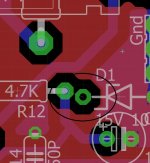
Use silver mica for 22pF and 680pF when you can, not ceramic!!
R18, R38 feedback loop is best low inductance resistors 0.5 watt or 1 watt low inductance carbon.
R30 is a 1 watt resistor.
R12, R13 is 0.5 watts.
R32 is ntc resistor connection for thermal compensation and R17 parrallel is for adjustment how much compensation you need, maybe first small pot 47 or 100 ohm on a 10- 22 ohm ntc, try first just short and see how it do keep idle, the drivers on the heatsink seems to do tracking in sim.
R16, R19, R20 is 0.5 watts
R11, R4, R10 is 0,5 watts
R28, R29 is 2 watts, (most modern metalfilm are 3 watts that is oke).
The rest are normal 0.25 watts, but as you look at schematics you can see where thee are.
This amp has current feedback, these amps can be extremely fast, and no TIM distortion who is the most severe to damage the sound quality, voltage feedback do introduce TIM, that is why maybe the feedback is not a problem but that distortion as this let amps sound so clinical and hars.
Other problem with current feedback is the temp runout on offset, however, it is a circlotron and so when this runout is equal then because of opposite fase it can cancel out ;-).
When this is not the case it needs a servo, and maybe even a double one, so lets hope it do option one.
Resistor dissipation is measured in sim on full power, to be shure, so it has to be oke .
So goodluck.
Last edited:
Kees,
What do you suggest for the temperature compensation resistor? A thermistor a la Pass F5? But your guess is that the IRFP 610 mounted on same heatsink already provides this function?
What do you suggest for the temperature compensation resistor? A thermistor a la Pass F5? But your guess is that the IRFP 610 mounted on same heatsink already provides this function?
Kees,
What do you suggest for the temperature compensation resistor? A thermistor a la Pass F5? But your guess is that the IRFP 610 mounted on same heatsink already provides this function?
It is just a case of experiment, do use a low ohmage thermister or a la Pass what is worth experiment with, do not disturb the driver capability, maybe the 120 ohm some lower and the resistor higher, here we need also experiment, and look it go with positive or negative thermistor action.
10 ohm and 100 ohm pot parallell to tune runaway such it will correct right.
PS I have not tick infection happenly.
regards
Last edited:
Good news on the tick business. Is that same as Lyme's disease? Where I live we are really prone to tick infection called Lyme's disease. It's incurable if not caught in time but can be treated with antibiotics if caught early. All the deer and rabbits and squirrels here are infested with Lyme's disease ticks. You cannot go for a hike in the woods without massive bug repellent and long pants and long sleeve shirts. Nasty bugs. They are carried by native "Lonestar Tick":

Many of my neighbors have contracted Lyme's disease.
Many of my neighbors have contracted Lyme's disease.
I did get Lyme Disease positive bloodwork, however the blot who she do afterwards to be shure it is not false positive, who was negative, and so it was false positive.
We have here woods where lyme is not so much , 10 procent of ticks are infected, in the north of holland there is al lot more, not in woods but grass land, mouse and ratts are the carriers and in woods mouse and sqirrels.
regards
We have here woods where lyme is not so much , 10 procent of ticks are infected, in the north of holland there is al lot more, not in woods but grass land, mouse and ratts are the carriers and in woods mouse and sqirrels.
regards
Attachments

Last edited:
As you see is eagle not capable to warn with erc for open airwires.
it give board consistent while it is not.
so I have to carefully search for open connections, X your pcb is already controlled for this, but all the other pcb software do give errors and place where open connections excist eagle do not.
regards
it give board consistent while it is not.
so I have to carefully search for open connections, X your pcb is already controlled for this, but all the other pcb software do give errors and place where open connections excist eagle do not.
regards
Attachments
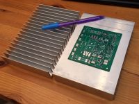
Heatsinks are in. 7.28in x 5.00in x 1.0in fins.
Is this a pure class A amp? How watts of dissipation do I need?

Looks very good, here is a calculator for the heatsink.
for class a amps you need to bias in the middle of its load line, for 50 watts you have minimum 100 watts disipation or arround there.
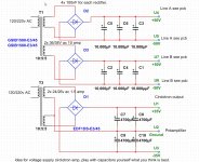
For the supply, the drivers 1 amp max is enough and power amp circlotron you have enough on the mentioned power.
for the circlotron you now it has two floating supply,s who are referenced by two resistors for the driver section, just let now how much elco,s and such you want use and I drawn the supply. you need to separate driver and circlotron completely, the driver section has just the normal technololy of supply,s. and circlotron two independent ones plus and minus.
regards
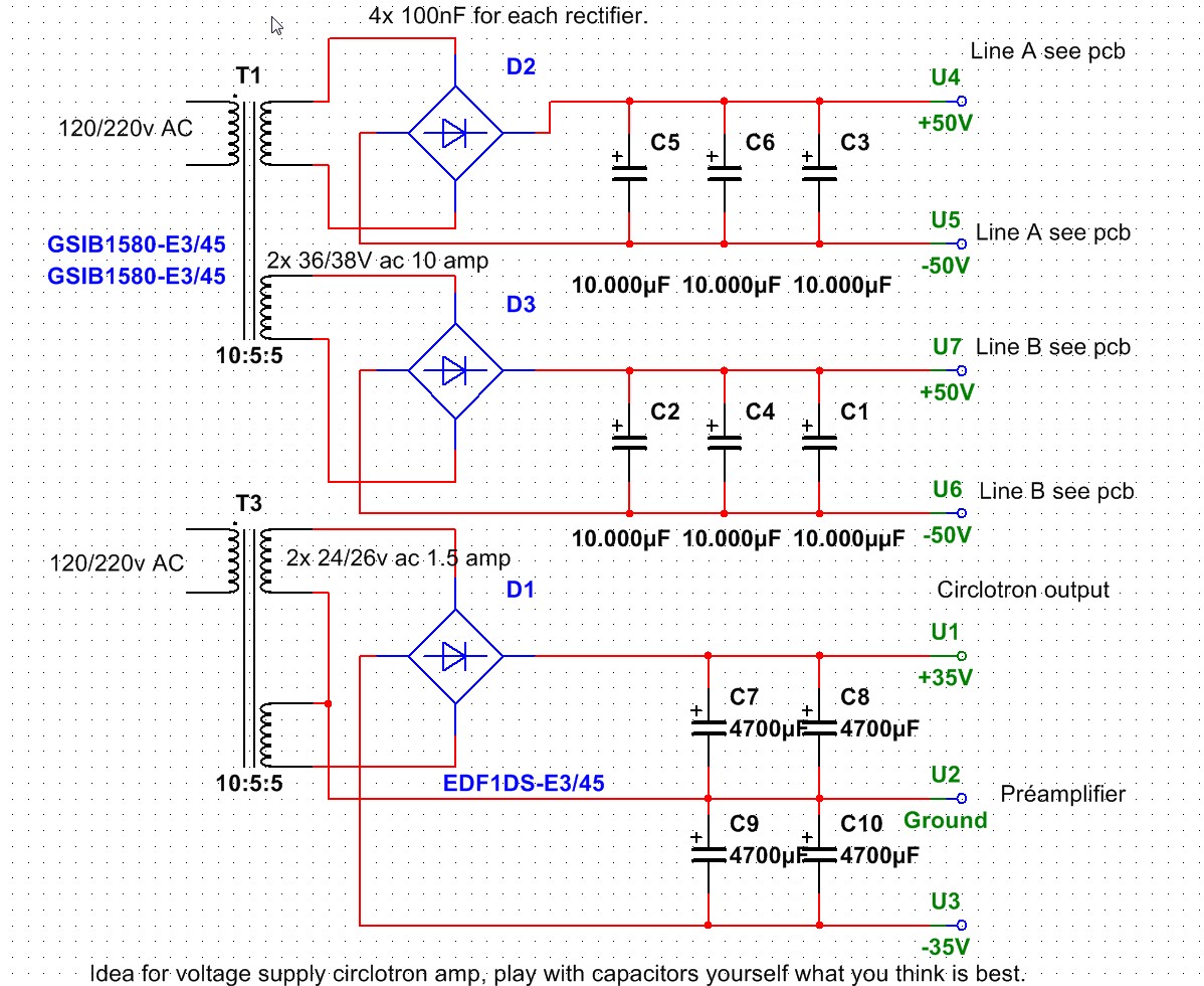
Hi X I have received your pcb,s these look very nice, here I have also a drawn about the supply line A belong to the same supply, have this done for easy recognizing. for the capacitors you can yourself decide how much you want.
possible you need a stabilized preamp voltage to get immunity for the supply lines and so possible supply noise, with two 1.5 amp regulators you are done, but try this first, maybe it do well, use 2 x 4700 uF here each line.
regards
possible you need a stabilized preamp voltage to get immunity for the supply lines and so possible supply noise, with two 1.5 amp regulators you are done, but try this first, maybe it do well, use 2 x 4700 uF here each line.
regards
Attachments
Last edited:
Kees,
I'm glad the boards got to you safely. Do you have all parts to start building? I will have to place an order on Digikey for the transistors as my order from Ali is taking way too long this time. Thanks for the diagram. So each amp board requires both the A and B PSU's. This means that I need to make 4 of the 50v PSU's for two channels then? On the 35v circuit you show 25v secondaries in series - that would be too much. I think you mean dual 12v center tap secondaries for 24v, or if I have dual 25v secondaries each one can be used for a channel to get the 35v. I think I got the wrong 25v trafo for this - it's a tiny 10VA one - looks like I needed at least 50VA?
I'm glad the boards got to you safely. Do you have all parts to start building? I will have to place an order on Digikey for the transistors as my order from Ali is taking way too long this time. Thanks for the diagram. So each amp board requires both the A and B PSU's. This means that I need to make 4 of the 50v PSU's for two channels then? On the 35v circuit you show 25v secondaries in series - that would be too much. I think you mean dual 12v center tap secondaries for 24v, or if I have dual 25v secondaries each one can be used for a channel to get the 35v. I think I got the wrong 25v trafo for this - it's a tiny 10VA one - looks like I needed at least 50VA?
I have al parts for building, except the J113 who go be a J112 with higher Goss, I have a j103 also maybe this can work also and later correcting.
the a and b voltages is because then you see how to connect, the connectors are crosslinked because of pcb design making it easyer.
Here you can calculate trafo voltages and such, you need 2 x 35 volts for pre-amp and 2x 50 volts for circlotron. 28 volts input give 36,4 volts.
one insolated voltages for circlotron and one symetrical for preamp.
Online Calculator .:. Linear Power Supply Designer
This supply is for one complete channel, but you can connect stereo boards on supply.
I go take the pc driven supply who can put out two supply with max 3 amp and 35 volts, can adjust current and voltages so testing is easy step by step.
Pity that my mosfets are not delivered to you, postoffice here did respond on twitter, she do not like negative responses, and need some more info, maybe she do get by you
if it was lost first.
regards
Last edited:
You may finish your build faster than me. Maybe I place the Digikey order for MOSFETs then...
Ok, so do I need to make qnty 4 x 50v supplies (but one 300VA toroidal trafo with split supply) for a pair in stereo? Or do you mean connect 2 amp boards to the 2 50v psu boards?
Ok, so do I need to make qnty 4 x 50v supplies (but one 300VA toroidal trafo with split supply) for a pair in stereo? Or do you mean connect 2 amp boards to the 2 50v psu boards?
For real high end you need supply for each channel but you can also just connect stereo on one 2x 50 volts supply, for your need 10 amps is enough.
the preamp the same, just 2 x 35 volts, what you can do to insolate is use 4 regulators on one supply board and put preamp channel on two of them just supply out to regulator (1.5amp) and another one the same, afcouse for plus and min channel, each regulator his own preamp board, so two for one channel making a quite good supply with high ripple reduction and insolation making us of one supply is then enough..
An I have to go to police station, nabure has complaned about me, I think security camera,.
I just realized I already have a 250va 25vac trafo so can make lots of 35v for this amp. I will use my 300va 32vac trafo for the 44v main supply. I still need to order the IRF610/9610's though. Otherwise could be building already. Just as well as the Pass M2 is borrowing the heat sinks at the moment and I want to listen to that for at least another week.
stereo amp needs 4 isolated 50v supplies, the +-35v can be shared for both channels
It is not possible to connect two circlotrons on one 2 x 50 volt supply? just paralell them or give the floating character of a circlotron offset pumping problems when play louder?, there is a ground reference with resistors but maybe it is nog enough to prevent things.
I think when using separate preamp/driver supply the circlotron channels can be parallel on one 2 x 50 supply, just be carefull with speaker cables though, don't let your dog or wife sniff on them.
For real high end we need separate supplys.
I just realized I already have a 250va 25vac trafo so can make lots of 35v for this amp. I will use my 300va 32vac trafo for the 44v main supply. I still need to order the IRF610/9610's though. Otherwise could be building already. Just as well as the Pass M2 is borrowing the heat sinks at the moment and I want to listen to that for at least another week.
The irf610 and 9610 and zvn/zvp4424a was on the package I did sent to you, strange it is not delivered, while when I order in China almost always I get it and a modern postoffice like in USA do lost them.
I do also need to build a supply the 35 v voltages comes from a regulated laboratorium supply for testing, I go try sunday to see what happens, you can then just take over without testing if we are lucky. I use carbon resistors, do sound better.
regard
Attachments
Last edited:
sharing output supplies would short the outputs of the channels to each other
I have not even see it this way, and as you see the simplest things are the toughest.
Thanks for sharing.
X seek a extra transformer, it is the best way anyway. I have found two transformers, two ring transformers with one 2 x 22 volts 2,7 amp and one with 2 x 35 volts 5 amps. Enough to go testing, however the hybride in my home has a 2 x 65 volts supply from a old 400 watts amplifier who has ring emitters in amplifier but was blown and damaged, so I use the supply and speaker protection from there.
regards
- Home
- Amplifiers
- Solid State
- allFET circlotron