Also, while doing some research on a completely unrelated project, I stumbled across this... a nice ADC/DAC board using the very AD1938 that I am planning on using... Ready to roll. He provides links to get the PCBs for cheap and a saved BOM on Mouser's website ready to order (save for a component or two that need to be swapped due to no longer being stocked, at least in the USA).
Check it out.. Linux-Based Low-Latency Multichannel Audio System (CTAG face2|4) | Creative Technologies
Looks interesting. Especially the way they work and their ability to design hardware and software. It they could get some interest in using the type of MCU we consider here, they could get the project one level higher, with added capes and so on...
Maybe it would be interesting to contact them to ask about their interest in such idea. In the potential projects, they already consider the stm32F4 discovery.
JMF
Indeed, however AudioWeaver from Paul Beckmann is not the only approach to be watched.Hi, I use the version provided by Audioweaver. I understand that it allows freely to work with some development boards as the Stm32F4 Discovery board. So I found it perfect for early proof of concept, but not scalable to multi amplification, or to other Nucleo boards with M7 core.
Have you looked Teensy from Paul Stoffregen (and IBM Node-RED)?
You may try becoming "Teensy Audio" compatible, and from there, become multichannel.
- https://forum.pjrc.com/threads/24793-Audio-Library?p=50653&viewfull=1#post50653
- Node-RED
- https://www.pjrc.com/teensy/gui/
- Special thanks to Nicholas O'Leary, Dave Conway-Jones and IBM. Without their work on the open source Node-RED project, this graphical design tool (Teensy Audio) would not have been possible!
- Node-RED
- https://www.pjrc.com/teensy/gui/
- Special thanks to Nicholas O'Leary, Dave Conway-Jones and IBM. Without their work on the open source Node-RED project, this graphical design tool (Teensy Audio) would not have been possible!
Have you looked Benjamin Larralde, suggesting that it is possible to export the Teensy Audio engine to Arduino :
- https://www.hackster.io/blog/teensy-audio-library
- Teensyduino: Download and Install Teensy support into the Arduino IDE
- Teensyduino: Download and Install Teensy support into the Arduino IDE
By the way I'm not sure that those solutions will help audio DSP becoming popular. As I said many times, I see more value into a simple stand-alone program running on a STM Nucleo board, properly initializing the CPU, the clocks and the I2S interfaces, properly executing a couple of 32-bit FIR filters operating in parallel, not relying on audio buffers.
The audio output can be as simple as feeding a couple of assembled PCM5102A DAC boards like PCM5102 DAC Decoder I2S Player 32bit 384K Assembled Board A2 012 | eBay using I2S.
The audio input can be as simple as :
- an assembled USB->I2S converter board like Assembled USB TO Spdif Coaxial I2S SA9023 Processor Chip 24bit 96K DAC | eBay
- an assembled SPDIF->I2S converter board like Assembled Coaxial Optical Receiver Board TO IIS I2S Output CS8412 FOR Amplifier | eBay
All the rest, I mean the bells and whistles of a GUI, look futile to me.
You better ask yourself how to determine the required FIR filter coefficients.
You'll realize that you require a microphone, and several analog inputs, and some DSP culture (what's a transfer function in gain and in phase, what's a FFT in gain and in phase, and what's the meaning of an inverse FFT), far more than shining bells and whistles. The assembled AD1938 board pointed by Sh0velman is your best friend. Let's hope it gets widely available.
Regards,
Steph
Last edited:
Thanks Stef,
This looks really interesting. I bookmark the thing. Teensy uses the same type of ARM cores we are working on. The DSP libs are the same. Maybe some code may be reusable. I didn't digged in the topic, but is it not clear to me how they mix C code and arduino stuff.
A comment on your Inputs/output proposals:
I agree with the output with I2S to DAC using assembled boards. But I have a concern with the SPDIF one.
The system should have a single clock. In my mind, the music "server" is often a PC, RPi or other, and has a not so good clock and a lot of software layers. So we don't want to rely too much on that time reference. But the Stm32 seem to me to have poor resampling capability. It seems that there are ST libs to upsample from 48>96>192 (and also 44.1>48). I found the applications notes, but not the firmware. So I don't know how to do ASRC. So it may be difficult (very very difficult?) to cleanly isolate the SPDIF input time domain from the board time domain.
Async USB helps to have only one time domain.
JMF
After investigations, it seems that it is not a question of CPU power. This is good news (as it would have been a potential show stopper).
I must investigate further to find the issue. I look at the concurrent access to the ring buffer...
JMF
I must investigate further to find the issue. I look at the concurrent access to the ring buffer...
JMF
Indeed, Asynch USB audio implemented on the ARM Cortex-M4 or M7 (Nucleo boards) or possibly ARM Cortex-A8 (BeagleBone) is a kind of software solution. The advantage is the zero hardware cost (however demanding a capable CPU). The disadvantages are a) the cost of a DSP-enabled microcontroller having a capable USB interface, b) the need for lots of MIPS ensuring a fast USB protocol handling and short interrupt context save/restore, and c) the obligation to comply with existing USB audio drivers for Windows XP, Windows 7, MacOs, Linux, iOs, Android.The system should have a single clock. In my mind, the music "server" is often a PC, RPi or other, and has a not so good clock and a lot of software layers. So we don't want to rely too much on that time reference. But the Stm32 seem to me to have poor resampling capability. It seems that there are ST libs to upsample from 48>96>192 (and also 44.1>48). I found the applications notes, but not the firmware. So I don't know how to do ASRC. So it may be difficult (very very difficult?) to cleanly isolate the SPDIF input time domain from the board time domain. Async USB audio helps to have only one time domain.
A PIC32MZ chip may perform better than a ARM Cortex-M4 chip or ARM Cortex-M7 chip, thanks to the shadow register set of the PIC32MZ architecture. This enables a zero overhead context save/restore, when the software needs to switch between USB audio handling, and DSP audio handling. This is the kind of feature you can benefit, by programming in "bare metal" style. As currently, there are only two software development environments for the PIC32 (the genuine Microchip one, and the one from Mikroelektronika), one can hope that the "bare metal" programming style is well supported. Unfortunately, there are no assembled boards available, featuring a PIC32MZ chip, equivalent in price and functionality to the numerous STM Nucleo boards featuring STM32F4 chips, and STM32F7 chips.
By the way, one should reverse engineer some Bose products (stand-alone speakers) in order to determine what kind of chips they embed : PIC32, or XMOS, or ADI SigmaDSP, or possibly ARM Cortex-M4 or M7. Seeing Bose becoming seduced by the ARM Cortex-M4 or M7 would mean something, don't you think ?
You can always rely on hardware solutions, relying on a specialized chip for materializing a good USB audio -> I2S interface.
- The Pavouk PCM2706 board is here : PCM2706 USB DAC with I2S just as theoretical example, for showing the kind of specialized chips we can rely on, and in such case there is an audio buffer and an analog PLL inside the PCM2607 chip, for generating a master audio clock that's long-term adapting to the audio clock carried by the USB, which is absolutely mandatory when the USB audio modality is neither async, nor adaptive.
- The eBay PCM2706 assembled board is here : PCM2706 USB Decoding Module USB to I2S DAC Decoder Headphone Amplifier DIY | eBay ready to use, exposing the I2S lines on a header.
- the eBay assembled CM6631A board is here : Assembled CM6631A USB to SPDIF Support Coaxial Optical Output 24bit 192K Fullnew | eBay ready to use, exposing the I2S lines on a header. This one supports the USB audio async modality. Please note the two quartz, one for the 44.1 family, and the other for the 48.0 family. This means no PLL, which guarantees a high quality master audio clock
- the MiniDSP USBStreamer relying on a XMOS chip is here : https://www.minidsp.com/products/usb-audio-interface/usbstreamer ready to use, exposing the I2S lines on a header. This one also supports the USB audio async modality. Please note, there is only one quartz whose frequency is correlated to the 48 MHz USB frequency, meaning that the master audio clock is deriving from a PLL, meaning that such master audio clock may not be as good as the one originating from a CM6631A solution.
In order to assess the quality of a homemade software-based USB audio interface, you shall measure and compare the three hardware-based solutions : PCM2706, CM6631A, XMOS.
Then, you shall measure your homemade software-based USB audio interface, and tell us where it fits. Do you have access to the required measurement gear?
Regards,
Steph
Last edited:
Then, you shall measure your homemade software-based USB audio interface, and tell us where it fits. Do you have access to the required measurement gear?
Regards,
Steph
Unfortunatly, I have no specific measure,ent gear :-(
JMF
Indeed, Asynch USB audio implemented on the ARM Cortex-M4 or M7 (Nucleo boards) or possibly ARM Cortex-A8 (BeagleBone) is a kind of software solution. The advantage is the zero hardware cost (however demanding a capable CPU). The disadvantages are a) the cost of a DSP-enabled microcontroller having a capable USB interface, b) the need for lots of MIPS ensuring a fast USB protocol handling and short interrupt context save/restore, and c) the obligation to comply with existing USB audio drivers for Windows XP, Windows 7, MacOs, Linux, iOs, Android.
Steph
ODROID C2 is not so expensive and can output 2 I2S it means 4 channels.
The ARM CPU is capable of 7.1 I2S OUT unfortunately there is no implementation 🙁
ODROID C2 is not so expensive and can output 2 I2S it means 4 channels.
The ARM CPU is capable of 7.1 I2S OUT unfortunately there is no implementation 🙁
I'm currently trying to port some code for Async USB to the Stm32. This is more difficult than I expected as the code that I have relies on old USB libraries from 2011 and not yet on the LL_XX uptodate libraries. I hope to be able to work it out for 48k and 16 bits). This would be a nice step forward.
About the Odroid C2: are the Linux drivers able to drive the 2 I2S and are the pins "exposed" ?
JMF
2 I2S ports are exposed (I asked Hardkernel in its forum) that allows 4 channels.
I am not sure, but I think linux drivers can drive 2 I2S instead 1. I didn't investigate.
Indeed. In the absence of a proper 256 x Fs clock input dedicated to audio, in case the Amlogic S905 works as master audio clock, it should generate a lot of jitter and possibly remain unable to generate exact audio clocks because of relying on its CPU quartz and PLL.ODROID C2 Amlogic S905 is capable of 8 x I2S-out.
A proper audio use of the Amlogic S905 would consist of defining it as slave what's regarding the audio clock. The Amlogic S905 would read the left/right clock and data clock, that are provided by a 8-channel DAC acting as master audio clock. A high quality quartz oscillator would provide the 256 x Fc MCLK to such DAC. The 8-channel DAC would output the left/right clock and data clock to the Amlogic S905.
What's regarding the audio input, the Amlogic S905 can act as async USB audio soundcard, in plain stereo.
Considering what's above, one should not use the Amlogic S905 as SPDIF receiver. The SPDIF clock that's imposed will always differ from the local 256 x Fs quartz. A possibility is to rely on a ASRC for resolving the clock conflict.
In case you don't want to mess with some ODROID C2 audio shield hosting a 256 x Fs clock and 8-channel DAC, there is always the possibility to output the 8-channel audio through USB. Simply hook a 8-channel USB2 sound card like the ASUS Xonar U7, and you are done.
The 8-channel USB2 soundcard possibility is the reason nobody is trying to implement the 8 x I2S capability of the Amlogic S905.
In case the audio is coming from WiFi or Ethernet, the ODROID C2 has enough processing power for acting as a) audio streaming receiver, b) stereo crossover, c) USB2 audio source feeding a ASUS Xonar U7 soundcard. This way, the audio crossover looks like a "filter" to be inserted after KODI, just before the operating system attempts delivering the audio on the USB2, to the ASUS Xonar U7.
At the end of the day, you realize that since ages, any Linux SBC equipped with Ethernet or Wifi, and equipped with a USB2-host connector, can theoretically act as Linux audio crossover, provided the people in charge of maintaining XBMC/KODI, specify some "addon" interface.
However, you shall not expect such XBMC/KODI "addon" interface, to allow your crossover plugin to operate in a "setup" mode, reading audio from mikes and comparing the actual Bode plots with some target Bode plot, for determining the FIR filter coefficients that are required. This seems to fly above the heads of the people in charge of maintaining XBMC/KODI. They didn't want to take responsibility, adding complexity to XBMC/KODI in allowing an option that's going to be exploited by less than 1% of their user base. This is exactly what they told me. I didn't succeed making them understand, that the required complexity is going to sit, not into XBMC/KODI, but inside the "plugin" or "extension" they need to allow. What a pity !
Indeed, starting from November 2011, I interacted with XBMC/KODI people on XBMC forum, telling them about crossovers. Please take some time reading this : diyAudio DSP plugin
You'll discover the mentality of software developers in Germany, back in 2011, and their attitude towards people dealing with audio.
The XBMC/KODI software developers first ambition is to embed some huge audio-video codec package into XBMC/KODI, ensuring it works "out of the box" without the user needing to fiddle with obscure parameters.
Their second ambition is to allow customized menus, as skins to be downloaded.
I can easily understand that they are so busy working at this, coping with audio-video codecs updates and upgrades, coping with user requests about the GUI cosmetics, that they don't have enough time for caring about audio "addons".
I interacted with several XBMC/KODI programmers, on the official XBMC forum. None of them could take the responsibility, explaining to me where XBMC/KODI makes stereo audio publicly available, that a third-party application "addon" can process and expand to 8-channel audio, that one can output using USB audio to a Asus Xonar U7 soundcard. They kept telling me in vague terms "this is already feasible", however remaining incapable to point actual and practical implementations.
None of them could tell me, if in such scenario, XBMC/KODI got designed to remain in charge of sending the 8-channel audio to the USB audio peripheral. This created a conceptual mess.
Some came to the conclusion that a third-party application should be considered by XBMC/KODI as a software block taking audio from XBMC/KODI, then delivering edited audio back to XBMC/KODI, properly telling XBMC/KODI how many channels-in, and how many channels-out, for helping XBMC/KODI selecting the right audio output modality (Linux driver interfacing issue).
Some came to the conclusion that all this was already possible using the existing "addon" paradigm supported by XBMC/KODI.
Some (like me) came to the conclusion that one should dig into their brand new ActiveAE "audio engine" before investigating deeper. Read this : Testing audio engine ActiveAE
Soon after, in April 2014, wisler, a Team-Kodi Member located in Germany, worked on adding an Audio DSP Plugin to the "AddonManager" of XBMC/KODI. Read this : Adding Audio DSP Plugin to AddonManager
Unfortunately, he intended to raise a new audio DSP standard, instead of allowing a plain VST or pseudo-VST to get inserted into the audio path. What a pity, again !
As soon as the STM32F4 discovery board appeared, I went away from Linux SBCs and XBMC/KODI staff. A few months later, the launch of the STM Nucleo F4 boards confirmed that there was something out, more open than fiddling with Linux and SBMX/KODI. The same positive feeling came again, when STM launched the STM Nucleo F7 boards.
My initial idea was to hook a WM8580 Codec (SPDIF-in, good PLL, 6-channnel out) on a STM Nucleo F401 or F411 board.
In the early days, the STM CubeMX software didn't exist. Consequently, for inexperienced people like me, it was virtually impossible to configure the STM 32F401 or STM32FF411 pinout, clocks, and I2S peripherals.
On top of this, soldering SMDs like the WM8580 chip, was difficult and hazardous.
Nowadays, the STM CubeMX software exists. It solves the configuration issue.
Nowadays, the possibility exists of grabbing stereo audio thanks to assembled SPDIF or USB audio boards available on eBay, and outputting many audio channels thanks to assembled PCM5102A DAC boards, also available on eBay.
Nowadays, power amplifiers embedding the DACs are a reality, like the TDA7801 and the STA326 or STA350.
Hope this helps you, not getting trapped in the SBC + Linux + XBMC/KODI phenomenon. This being said, the day the XBMC/KODI staff recognizes an audio crossover for what it really is, including how to setup it, I may change my opinion. What's the actual status, in august 2016? Are there new posts in the XBMC/KODI forum, dealing with audio crossovers?
Cheers,
Steph
Well...
1/ I didn't see ODROID C2 can not work as I2S slave 🙁
2/ I don't like kodi for audio
3/ I don't like USB for sound
4/ I like Linux, MPD, a real time kernel and something like Brutefir.
5/ If you prefere KODI I think you can pipe the sound to Brutefir.
6/ Last time I tried to mix HDMI out for video and something else for audio with Kodi I had bad results.....
Great stuff. Thanks for the indications. I'm glad to see somebody confirming the precautions one must take, when using SBCs for qualitative audio. I'm glad to hear that one can configure a ODROID C2 SBC as I2S slave (audio clock slave).Well...
1/ I didn't see ODROID C2 can not work as I2S slave 🙁
2/ I don't like kodi for audio
3/ I don't like USB for sound
4/ I like Linux, MPD, a real time kernel and something like Brutefir.
5/ If you prefere KODI I think you can pipe the sound to Brutefir.
6/ Last time I tried to mix HDMI out for video and something else for audio with Kodi I had bad results.....
Before going to much out of thread (we are supposed to deal with STM32 microcontrollers), can you please describe your sound reproduction arrangement, and tell us if there is a possibility for implementing a stereo 2-way crossover, in case one can exploit the two I2S channels that are exposed.
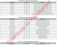
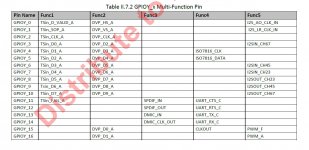
By the way, I am in search of somebody able to exploit the Func5 feature, for exposing the remaining two I2S channels, for outputting 8-channel audio. See the attached pictures.
Can you watch a movie, and apply a DSP crossover on the stereo downmix?
Many thanks,
Steph
Attachments
Great stuff. Thanks for the indications. I'm glad to see somebody confirming the precautions one must take, when using SBCs for qualitative audio. I'm glad to hear that one can configure a ODROID C2 SBC as I2S slave (audio clock slave).
Before going to much out of thread (we are supposed to deal with STM32 microcontrollers), can you please describe your sound reproduction arrangement, and tell us if there is a possibility for implementing a stereo 2-way crossover, in case one can exploit the two I2S channels that are exposed.
By the way, I am in search of somebody able to exploit the Func5 feature, for exposing the remaining two I2S channels, for outputting 8-channel audio. See the attached pictures.
Can you watch a movie, and apply a DSP crossover on the stereo downmix?
Many thanks,
Steph
I am not a good electronic guy, but I am good in computer language. I can make STM32 programs as well as linux program or drivers.
Currently, I think the best way to watch a movie with DSP is.... a video amplifier like Denon or Yamaha. This is what I have.
Audio quality is another aspect.
What market offers is really good for audio quality.
Currently, I have MPD, raspberry pi 2, a hifiberry DAC and my mobile phone to play music. I tried brutefir 3 years ago, but RPI was to slow. Now with RPI3, it can be perfect...
REW is a usefull tool for DRC, and Umik 1 is not so expensive. I have both.
Another intersting way should be to use the last TI DAC PCM5242 with embedded DSP and develop a web/android frontend as driver. Not so complicated.
For video, To do something on this way, we need a team project. As of now, it is too big for 1 or 2 people. We need electronic guys, dedicated dsp, coders in many languages,...
With a team it is really easy to do better than Denon or Yamaha offers to people. I have this idea for an open source project. Maybe next year.
The required software shrinks to almost nothing by relying on a stock audio/video software player (XBMC/KODI, etc) delivering a stereo signal, that you can output using the USB audio modality. You then grab such audio using an assembled USB -> I2S board (from eBay), conveying the I2S to the STM32F4 or STM32F7 Nucleo board running as I2S slave. The Nucleo board explodes the audio in three I2S. You then connect three assembled PCM5102A DAC boards (from eBay) running as I2S slaves for feeding two three-way active speakers. This should be a 1 man 1 week project. At this stage, anything more complicated looks futile to me.For video, we need a team project. As of now, it is too big for 1 or 2 people. We need electronic guys, dedicated dsp, coders in many languages,...
With a team it is really easy to do better than Denon or Yamaha offers to people. I have this idea for an open source project. Maybe next year.
Clearly, if the goal is to achieve a low jitter using a STM microcontroller, the obvious solution is to purchase some excellent assembled audio USB -> I2S board (from eBay), acting as master audio clock for both the STM32, and the DACs.
The required software shrinks to almost nothing by relying on a stock audio/video software player (XBMC/KODI, etc) delivering a stereo signal, that you can output using the USB audio modality. You then grab such audio using an assembled USB -> I2S board (from eBay), conveying the I2S to the STM32F4 or STM32F7 Nucleo board running as I2S slave. The Nucleo board explodes the audio in three I2S. You then connect three assembled PCM5102A DAC boards (from eBay) running as I2S slaves for feeding two three-way active speakers. This should be a 1 man 1 week project. At this stage, anything more complicated looks futile to me.
Clearly, if the goal is to achieve a low jitter using a STM microcontroller, the obvious solution is to purchase some excellent assembled audio USB -> I2S board (from eBay), acting as master audio clock for both the STM32, and the DACs.
"if the goal is to achieve a low jitter using a STM microcontroller"
It is not my target.
I respect yours : Hope you'll succed.
ps: I found a lot optimisation in the C code provided here.
As I think forums is a also a learning place, here are the main tips:
- Use pointers! And Use befferized pointers!
- Avoid constant test in loops
- externalize outside loops all what you can.
=> In a word, simplify loops.
If you need help I'll post optimized code.
I guess you are talking about the IIR Biquad filter routine, or the FIR filter routine. Am I right?I found a lot optimisation in the C code provided here. As I think forums is also a learning place, here are the main tips: - Use pointers! And Use befferized pointers! - Avoid constant test in loops - Externalize outside loops all what you can. => In a word, simplify loops. If you need help I'll post optimized code.
Have you tried the ones provided in the ARM CMSIS DSP library?
When you say "use pointers", is it for avoiding copying audio data to the input of some IIR Biquad filter, letting the IIR Biquad filter compute the filtered audio data, then copying the filtered audio data to some other IIR Biquad filter, and so on?
What's a "bufferized pointer"?
I guess you are talking about storing consecutive audio samples in a buffer (say 256 audio samples), for processing them in a row, which causes 256 times less context save/restore load compared to some naïve audio DSP done on a sample-by-sample basis, each new sample triggering an interrupt service routine, where the audio DSP (assorted to a lengthy context save/restore) actually occurs.
What do you mean by "avoid constant test" in loops?
Are you talking about defining the test reference of a do ... while ... as a constant at compilation time versus defining the test reference of a do ... while ... as a variable in RAM (or CPU register) that you shall initialize just after power up?
Are you talking about "constantly testing" within a loop progression? If yes, are you talking about unrolling loops like the ones forming FIR filters?
Regards,
Steph
I guess you are talking about the IIR Biquad filter routine, or the FIR filter routine. Am I right?[/QUOTDE]
No. I am talking about this code:
http://www.diyaudio.com/forums/digi...eved-stm32-microcontroller-9.html#post4790537
No. To be honest, I found the leaning curve of the STM32 too slow, as I wanted infrared, GUI and DSP. I found STM32 not as easy as Arduino. But maybe now, time has changed 🙂Have you tried the ones provided in the ARM CMSIS DSP library?
If you need copy, well then.... You need copy 🙂When you say "use pointers", is it for avoiding copying audio data to the input of some IIR Biquad filter, letting the IIR Biquad filter compute the filtered audio data, then copying the filtered audio data to some other IIR Biquad filter, and so on?
Pointers allow to avoid arrays. Usually, it is faster or use less CPU registers.
If you manage >1 array, don't use a test inside loop. Use at least 2 pointers and swap after the loop.What's a "bufferized pointer"?
I guess you are talking about the code that's over there, relying on FreeRTOS. Can you please publish two very small software projects not relying on FreeRTOS that anybody can load on a STM32F4 Discovery, or a STM32F4 Nucleo, only crunching numbers ? This way, we'll test project A performance (no optimizations) against project B performance (fully optimized). There will be a lot to learn, from this.No. I am talking about this code:
http://www.diyaudio.com/forums/digi...eved-stm32-microcontroller-9.html#post4790537
Hi,
I'm still progressing on the Async USB audio. I should be able to test something this WE. In fact I 'm slowed down by the evolution in the stm32 ecosystem from previous std periph lib to new HAL libs (that came with the CubeMX tool).
The pieces of code I had found were with the old libs (USB and Timers), and I have to adapt them to the new ones...
Let's see.
I will post code on Github as soon as I have a working example. Here again, it is not stright forward for me. I thought that I would just have to drag and drop the code in the browsed, but it seems that I have to "connect" Eclipse to Github with a tool called eGit. Some new learning needed here also... Camelator, would you have knowledge on that point?
I still strongly believe that stm32 can do what I need: Async USB to multiple digital outputs with DSP 🙂
JMF
Hi,
I have no knoledge on git as I use SVN (old school fahion 🙂 )
But I'll have to do it, as I also have projects for STM32.
For now it is a little bit complicated to work more on it,
maybe next week
FYI: I didn't took the ime I expected, but I think your main loop can be simplify by :
for( i=n_samples ; i >0 ; i-- ) {
Usb_write_endpoint_data(EP_AUDIO_IN, 8,*p_audio_buffer++) ;
}
Or somethink very close to that
- Home
- Source & Line
- Digital Line Level
- Can low jitter be achieved with STM32 microcontroller