Should anyone be interested I have some spare, fully assembled 'nodac' boards available; I cant possibly use all the stuff I've accrued. These have been assembled from the last batch of PCBs from the group buy. I have one each of the single ended and balanced/flipflop boards.
I'm asking £10 for the single-ended board and £15 for the balanced, both plus paypal fee and postage. PM me if interested.
I also have a spare JLSounds USB to I2S board that I will be listing on Swap Meet (£35)
Ray

I'm asking £10 for the single-ended board and £15 for the balanced, both plus paypal fee and postage. PM me if interested.
I also have a spare JLSounds USB to I2S board that I will be listing on Swap Meet (£35)
Ray
Ray what USB-I2S are you using now, if you use it?
Still using JLSounds for USB but I've also had success running BBB/Botic as an HQPlayer NAA at up to 24MHz DSD (DSD512) so mixing and matching...
With the BBB you don't use PC, right?
I still use a powerful computer to run HQPlayer but with the BBB/Botic I don't need another low power PC to act as an NAA (to which the USB board connects)
I have all music stored in HiRez and I use Daphile as player, do you know if I can use BBB/Botic in place of the Vaio laptop?
I don't think so, the image downloads on the Daphile site are all X86 so for Intel platforms, BBB is ARM architecture.
BBB uses ALSA and I think is UPnP capable so if you have your music in a suitable UPnP library you may be able to stream to the BBB.
Ray
BBB uses ALSA and I think is UPnP capable so if you have your music in a suitable UPnP library you may be able to stream to the BBB.
Ray
I have all music stored in HiRez and I use Daphile as player, do you know if I can use BBB/Botic in place of the Vaio laptop?

Ray I see people using 47K between ground and signal after the LPF, what's the purpouse of this resistor?
Another Update on my NO DAC DSD experiments
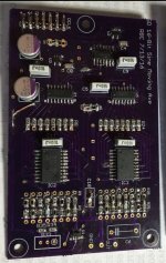
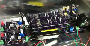
Attached are pictures of my circuit boards for the 16-bit sine wave moving average filter. The latest design uses SMD resistors to be within a 0.1% sine wave error. Also, the 1 and 0 signal durations are symmetrical within a 0.1% difference.
I am about 5 days into the break-in period. I can't hear any hiss from the JLS interface board. There have been short stretches of amazing music, but this all digital circuit has provided some of the nastiest SQ I have ever heard during a break-in. Another 10 days should let me know how good this design can sound.
I changed the RC filter resistor to increase the frequency roll-off to 100Khz and then 200Khz which improved the treble resolution, sound stage, and musical details. Removing the RC filter completely was a step backwards so some RC filtering is needed. I am still working on a adjustable LDR as part of the RC filter so I can make adjustments on the fly without introducing new parts.
Attachments
As I have been still receiving a trickle of requests about my No-DAC PCBs I had another small batch of the Balanced/FlipFlop boards fabricated and have a few spare - send me a PM if you're interested.
Ray
Ray
I changed the RC filter resistor to increase the frequency roll-off to 100Khz and then 200Khz which improved the treble resolution, sound stage, and musical details. Removing the RC filter completely was a step backwards so some RC filtering is needed.
Have you tried a higher order low pass filter?
see --> http://www.electronics-tutorials.ws/filter/filter_2.html
Have you tried a higher order low pass filter?
see --> Low Pass Filter - Passive RC Filter Tutorial
I have tried to find one that doesn' t mess with phase response so much but it is hard. Can you suggest some values?
Last edited:
NO DAC DSD experiments results
After 500 hours of break-in the music is amazing, but there is a negative sonic overtone which varies over time. This which may be caused by high frequency oscillation or noise somewhere. During my last circuit changes my DIY 5V Vreg failed putting 7+ volts into the JLSounds board after the isolator. Some of the signals from pins 11-20 didn't measure right, but it continued to put out the essential DSD signals. Maybe a damaged JLS board is the source of my sound issue.
A couple of days ago I discovered the Signalyst DSC1 DSD project which looks similar to what I attempted. It has a 32-bit equal weighted average circuit using the same shift register IC's that I used. It has an IV opamp and a 7th-order LP filter. It is designed to interface with the Amanero which can handle higher DSD rates than the JLS board. The DSC1 will be my next NO DAC DSD project with the Amanero board.
Last edited:
There's a thread on the Signalyst DSC1 here;
http://www.diyaudio.com/forums/digital-line-level/254935-signalyst-dsc1.html
I'm building a DSC1 using one of these boards;
DSC1 DAC DSD decoding hardware decoder suite supports Italy Amanero XMOS | eBay
and I also have a differential version of the board on order;
Differential Version DSC1 DAC DSD decoding hardware kit Italy Amanero XMOS | eBay
I plan to use a BeagleboneBlack running meiro's Botic software, via a separate isolator/reclocker board, to get the DSD input signals. With my Buffalo 3SE DAC I have been running at up to DSD512 with the Beaglebone and reclocker.
Ray
Did you use equal resistor values (rectangular window, as in DSC-1) or proportional to some window function? With equal values, the attenuation of this filter is close to nothing, and I can't get rid of hi-freq noise on quiet fragments of music.After 500 hours of break-in the music is amazing, but there is a negative sonic overtone which varies over time. This which may be caused by high frequency oscillation or noise somewhere. During my last circuit changes my DIY 5V Vreg failed putting 7+ volts into the JLSounds board after the isolator. Some of the signals from pins 11-20 didn't measure right, but it continued to put out the essential DSD signals. Maybe a damaged JLS board is the source of my sound issue.
A couple of days ago I discovered the Signalyst DSC1 DSD project which looks similar to what I attempted. It has a 32-bit equal weighted average circuit using the same shift register IC's that I used. It has an IV opamp and a 7th-order LP filter. It is designed to interface with the Amanero which can handle higher DSD rates than the JLS board. The DSC1 will be my next NO DAC DSD project with the Amanero board.
Ray I see people using 47K between ground and signal after the LPF, what's the purpouse of this resistor?
???
Attachments

it is run good, and good sound , but it is not the best design !
I think you need waite for we will finis all design!
thanks
- Home
- Source & Line
- Digital Line Level
- The Best DAC is no DAC