Terry,just what i noticed.Hi Hugh,
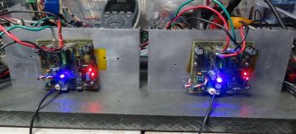
I installed a single blue LED and it is working perfectly. I had to install 100k for R5 in order to zero the offset with the 200R trimmer. I actually installed a 100k trimmer in place of R5 and centered VR1. I had the 100k maxed and it turned out to be about perfect so I just installed 100k resistors and now all is well. I have it running on +-44V right now because my variac went out last night. I will have to set up an adjustable PSU to do further testing because I don't have a 24-0-25vac transformer available right now. I can probably get by with the +-44V for some quick testing if I run it on 8 ohm speakers.
Stay tuned.
Blessings, Terry
Do not attempt to adjust the offset when amplifier start up.
Leave the amplifier to come hot and then adjust the 0 offset.
This topology without servo controller need stable thermo to keep offset near to zero.
A piece of polyourethane around the Q1 may be help
Hi Guys,
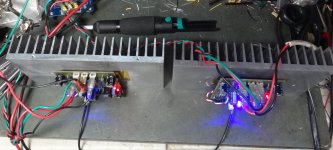
I have been listening for about a half hour. I hooked it up to my A/B setup so I could get a better feel for it. My impression so far is that is has its own sound. I compared it to a PeeCeeBee, an SKA GB150 and a DX Super A. It is milder than the PeeCeeBee and Super A but not as dark as the SKA. It kind of has a "fat" sound through the upper bass and mids. I kind of like it. Everything sounds good through it and without the A/B I may not have noticed the differences. I have them mounted on some smallish heatsinks, 3-1/4" X 7" X 1-1/4" but them seem to be fine. I'm listening at a descent level and they are comfortable to hold. I have th bias set with 40mV across R21. Q3 is pretty hot. I can just keep my finger on it. I'm not sure if that is because of the 44V rails or not. It's probably fine but if the layout is going to be adjusted at all I would leave room for a small heatsink.. As it is it is right up against the trimmer.
Thanks Christian for a cool little amp.
Blessings, Terry
Attachments
Thank you Terry and Thimios for tests
You use 2200uF in C4 ?
My PCB fits a heat sink in Q3 .
Best Regards
You use 2200uF in C4 ?
My PCB fits a heat sink in Q3 .
Best Regards
Hi Guys
Mosfets tend to be more nonlinear at low idle currents, plus the circuit is highly asymmetric requiring higher idle to achieve reasonable performance.
I would suggest that the CRC supply idea be abandoned. It is good to have large local filters, and the use of multiple filters rather than single large filters is favourable. Keeping the supply impedance low over the audio band is preferred, even though there are examples from pass, Cherry, and others using CRC and CLC supplies. Those tend to be for class-A amps, or in Cherry's case, to enhance stability of a layout that might have marginal stability.
Have fun
Glad to see another tested amplifier soonThank you Terry and Thimios for tests
You use 2200uF in C4 ?
My PCB fits a heat sink in Q3 .
Best Regards
Yes feedback cap value is 2200uf
Never i have noticed overheated Q3
Last edited:
Glad to see another tested amplifier soon
Yes feedback cap value is 2200uf
Never i have noticed overheated Q3
Did you put your finger on it?
No, but i will measure the temperature tomorrow.Did you put your finger on it?
I try to make a habit of touching all the transistors of a new amp. That is how I noticed it. It is not hot enough to smell hot. Like I said, it might be because of the 44V rails. I don't have a lower voltage PSU right now to test it with.
BTW 44v is a danger voltage for C5200I try to make a habit of touching all the transistors of a new amp. That is how I noticed it. It is not hot enough to smell hot. Like I said, it might be because of the 44V rails. I don't have a lower voltage PSU right now to test it with.
Hi Terry
With the simple bootstrap load, the current through Q3 is a function of rail voltage, and at 44V I'm not surprised that its running a little hot! 35V is about the most I would be comfortable without some form of heatsink, and on my own layout I've left room around the VAS transistor for a small U shaped clip on type.
I also like to keep Q1 well away from it and other heat sources, otherwise I find that the offset tends to wander as the amp warms up. Of course one should trim once warmed up, but then the offset will be off on cold start up. Its no big deal but I mention it in case people become concerned with perhaps 100mV offset across the operating range.
Thanks for the listening report 🙂
Hi Christian,
That makes sense. If I ever decide to build a case for this I will be sure to use a lower rail voltage.😉
That makes sense. If I ever decide to build a case for this I will be sure to use a lower rail voltage.😉
Thank you Terry, Thimios,
We are all getting a ringside view of this amp and its sound qualities!
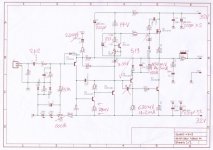
With 44V rails, Q1 has dissipation of 28mW, and runs cool. Q2 runs at 60mW, again well under the benchmark 100mW for a TO92. But Q3 runs at (44-4)/(2.2+1.2)x(44-4)= 432mW and that is HOT for a TO126. A small 32C/W flag heatsink would be good there to keep its cool. Benchmark for a TO125 I find is 350mW, higher than that and you need a heatsink. Warming transistors make the offset wobble......
Terry, no-one has more experience with amp sound than you (or speed of build BTW) so if you like it, and its 'fat' sound appeals, I'd reckon this must be a very good amp!
Because of the blurring of the crossover issue that bedevils complementary SS AB amps, and because of the quasi topology and the tweaks that Ranchu has implemented, I would think this amp would be very good for listening at low level through voice. It would be a really good amp for listening to the radio, in fact, maybe through your iPod. It should be very good for MP3/DAB music too, fattening out to remove the digititis.
The 3.3V zener is well replaced by a blue led since their tempco is close to zero. Nominally they are 2.6V, but some are more with nearly 11mA through them! I see it brightens up the heatsink! I like a few leds on my amps, it adds a bit of colour, and you feel kindly about an amp with a shining led on it.
Great work, thank you.
Ciao,
Hugh
We are all getting a ringside view of this amp and its sound qualities!
With 44V rails, Q1 has dissipation of 28mW, and runs cool. Q2 runs at 60mW, again well under the benchmark 100mW for a TO92. But Q3 runs at (44-4)/(2.2+1.2)x(44-4)= 432mW and that is HOT for a TO126. A small 32C/W flag heatsink would be good there to keep its cool. Benchmark for a TO125 I find is 350mW, higher than that and you need a heatsink. Warming transistors make the offset wobble......
Terry, no-one has more experience with amp sound than you (or speed of build BTW) so if you like it, and its 'fat' sound appeals, I'd reckon this must be a very good amp!
Because of the blurring of the crossover issue that bedevils complementary SS AB amps, and because of the quasi topology and the tweaks that Ranchu has implemented, I would think this amp would be very good for listening at low level through voice. It would be a really good amp for listening to the radio, in fact, maybe through your iPod. It should be very good for MP3/DAB music too, fattening out to remove the digititis.
The 3.3V zener is well replaced by a blue led since their tempco is close to zero. Nominally they are 2.6V, but some are more with nearly 11mA through them! I see it brightens up the heatsink! I like a few leds on my amps, it adds a bit of colour, and you feel kindly about an amp with a shining led on it.
Great work, thank you.
Ciao,
Hugh
Last edited:
Hi Hugh,
Thanks for doing the math. It backs up what I saw. I agree about the low volume sound. It is very good. I also listened to some Ella and some Gerry Mulligan and it is very pleasing. Folks who find accurate amps sterile will like this amp.
Thanks for doing the math. It backs up what I saw. I agree about the low volume sound. It is very good. I also listened to some Ella and some Gerry Mulligan and it is very pleasing. Folks who find accurate amps sterile will like this amp.
Bax resistor is now 120R according to your suggestion.Thimios,
All your voltages and currents look fine; only a polishing is needed!
1. I would suggest you straddle the Vbe multiplier and the zener with C7 (? - I am doing this on mobile phone lying in bed so can't easily check).
2. I estimate the quasi base is drawing 1.5mA so adding your measured 4.2mA we
have 5.7mA drawn through the phase inverter collector. You have 520mV across the Bax resistor and only 0.5mA drawn through the Bax diode.
When the nmos starts to switch on this diode will turn off swiftly and spray artefacts into the output node very close to the crossover point where discontinuities in the waveform are fatigueing. Solution: Increase the Bax resistor to 120 ohms.
Ciao
Hugh
Temperature on Q5=48 C(+/-32V ).
Attachments
Last edited:
Wow, Thimios, maybe it should be 150?
Then the resistor would pass 3.67 mA, and then the diode would pass 4.2+1.2-3.67 = 1.73mA and it would not turn on until the output voltage rises over 2.5V, well over the critical crossover area, since at this point an 8R speaker would be passing at least 312mA, where the switching would never be heard. Furthermore, with +20dB output, 14.14Vp into 8R, the mosfet NEVER turns off; it gets down to 3.6mA, staying on. At higher outputs, the mosfet does turn off, typically around 22Vp output (30W into 8R) so this situation prevails for quite a bit of higher output.
This is depending on 105mA quiescent according to LTSpice, so this is a simulation. I'd need to have your oscillograms to be absolutely sure of the reality of course. But it should be close......
Congratulations, very nice result!
Cheers,
Hugh
I will increase this to 150R and i report again🙂Wow, Thimios, maybe it should be 150?
Then the resistor would pass 3.67 mA, and then the diode would pass 4.2+1.2-3.67 = 1.73mA and it would not turn on until the output voltage rises over 2.5V, well over the critical crossover area, since at this point an 8R speaker would be passing at least 312mA, where the switching would never be heard. Furthermore, with +20dB output, 14.14Vp into 8R, the mosfet NEVER turns off; it gets down to 3.6mA, staying on. At higher outputs, the mosfet does turn off, typically around 22Vp output (30W into 8R) so this situation prevails for quite a bit of higher output.
This is depending on 105mA quiescent according to LTSpice, so this is a simulation. I'd need to have your oscillograms to be absolutely sure of the reality of course. But it should be close......
Congratulations, very nice result!
Cheers,
Hugh
Thank you Thimios!
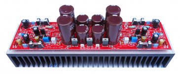
I'm about to birth a brand new SAKSA 85. It's been running two days on my bench, and I'm finishing the input/output wiring. I will take some piccies of the amp very soon for people interested. It is based on three of my commercial amps, and goes back to 2000 with the AKSA input stage.
I look forward to your 150R Bax resistor, Thimios..... who knows, I might build one of these too, they are wonderful at low output....
Ciao,
Hugh
Unfortunately this 150R Bax resistor solve one problem but a new one created.Welcome to instability country!😱Thank you Thimios!
I'm about to birth a brand new SAKSA 85. It's been running two days on my bench, and I'm finishing the input/output wiring. I will take some piccies of the amp very soon for people interested. It is based on three of my commercial amps, and goes back to 2000 with the AKSA input stage.
I look forward to your 150R Bax resistor, Thimios..... who knows, I might build one of these too, they are wonderful at low output....
Ciao,
Hugh
Gee, this is very odd....... I will go back to my LTSpice, I suspect we need to put in 47p across C to B on the phase inverter..... Damn.........
One down, another up. I got my SAKSA 85 going today. Absolutely wonderful, I'm thrilled with the bass, PRAT, and engagement. This is a fabulous amp.
Hugh
One down, another up. I got my SAKSA 85 going today. Absolutely wonderful, I'm thrilled with the bass, PRAT, and engagement. This is a fabulous amp.
Hugh
Attachments
No problem, i will try to add this capacitor again in circuit soon.Gee, this is very odd....... I will go back to my LTSpice, I suspect we need to put in 47p across C to B on the phase inverter..... Damn.........
One down, another up. I got my SAKSA 85 going today. Absolutely wonderful, I'm thrilled with the bass, PRAT, and engagement. This is a fabulous amp.
Hugh
This new amplifier looks nice!
- Home
- Amplifiers
- Solid State
- Very simple quasi complimentary MOSFET amplifier