I was wondering if one of such a heat-sink is sufficient for one channel or we will need more cooling?
D180-20 - AAVID THERMALLOY - Heat Sink, Square, For 80MM Power modules and Solid State Relays, 0.33 °C/W, 135 mm, 125 mm, 180 mm | Newark element14
regards
I would say at least 2 of those per channel. I would now with 3 of those side by side for each channel. with the aluminum bracket fixing to the 3. You can never have enough cooling!! 🙂
I would say at least 2 of those per channel. I would now with 3 of those side by side for each channel. with the aluminum bracket fixing to the 3. You can never have enough cooling!! 🙂
ok... many thanks!
ok... many thanks!
Check the dissipation capacity of the cases offered by the diyaudio store. you should have at least that per side.
The bracket should fit nicely with two of the heatsinks you linked, and give enough dissipation.
What temperatures do you usually have in the summer in your house?
Check the dissipation capacity of the cases offered by the diyaudio store. you should have at least that per side.
The bracket should fit nicely with two of the heatsinks you linked, and give enough dissipation.
What temperatures do you usually have in the summer in your house?
in summer we have most of the time max. around 24°c , but some few days up to 28°c in the listening room.
Why not just buy the deluxe 5u case from diyaudio store? You can buy directly from italy, it comes predrilled and is really easy to assemble.
4 of those heatsinks cost about 400euros, even the 5U chassis is cheaper than that with shipping.
4 of those heatsinks cost about 400euros, even the 5U chassis is cheaper than that with shipping.
Why not just buy the deluxe 5u case from diyaudio store? You can buy directly from italy, it comes predrilled and is really easy to assemble.
4 of those heatsinks cost about 400euros, even the 5U chassis is cheaper than that with shipping.
thanks for your suggestion. your are right; it was just if I am going to have my own housing design ;-)
The 4U deluxe case should be enough cooling... Only the Deluxe cases have drilling standard.
Last edited:
The 4U deluxe case should be enough cooling... Only the Deluxe cases have drilling standard.
thanks!
CSX1 & CSX2
Hi All,
In anticipation of the availability of the kits I've been reading and re-reading the Sony VFET articles, both part 1 and 2.
One Question I have is that in the schematics for CSX1 and CSX2 in the Part 1 Article, there is an 8R resistor at the output.
Anyone know if that is meant to indicate an 8 ohm speaker load or whether that 8 ohms is supposed to be in parallel to the speaker load? If parallel, why and what wattage rating?
Thanks!
Greg
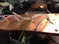
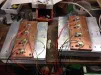
Totally off-topic, but here is my planned output stage mounting scheme for the flexible CSX/VFET projects. The goal was to avoid the cost of the angled extrusion as nearly anyone will CnC a piece of flat stock. I am not sure how well it will work, but we will see. It's mounted to a Conrad Heatsink in the photo through a piece of copper bar. I need to get properly sized teflon tubing for the TO-3 pins and screws and I think I am ready for some fireworks.

Attachments

In the CSX2 is necessary to connect this resistor or the speaker because the polarization of the sources of the Sits are made across this resistor.
how's that ?
yup , Papa is keen of making amps which are making BoomBigBadaBoom, when speakers is not connected

yup , Papa is keen of making amps which are making BoomBigBadaBoom, when speakers is not connected
how's that ?
yup , Papa is keen of making amps which are making BoomBigBadaBoom, when speakers is not connected
😀
Either the angle or this could be pretty easily hand drilled with a bit of patience
The holes for the pins seem small - might give extra fireworks!
The holes for the pins seem small - might give extra fireworks!
Totally off-topic, but here is my planned output stage mounting scheme for the flexible CSX/VFET projects. The goal was to avoid the cost of the angled extrusion as nearly anyone will CnC a piece of flat stock. I am not sure how well it will work, but we will see. It's mounted to a Conrad Heatsink in the photo through a piece of copper bar. I need to get properly sized teflon tubing for the TO-3 pins and screws and I think I am ready for some fireworks.
The holes for the pins seem small - might give extra fireworks! Either the angle or this could be pretty easily hand drilled with a bit of patience
As it turns out, they are drilled to the outside diameter of Teflon tubing (18 ga) per the TI TO-3 mounting spec, here:
http://www.ti.com/lit/an/sboa020/sboa020.pdf
Ah, you really did mean tubing! Here's the angle specs for the one pair per side. 1/4" aluminum "L" angle is pretty easy to find if you don't find the "t"shape. But it might help people making flat plates too...
http://www.diyaudio.com/forums/atta...68-sony-vfet-amplifier-part-2-diy-bracket.pdf
luvdunhills flat approach would give more room for a PSU probably.
Here's the pin spacers we used
http://www.mcmaster.com/#94639A300
They are shorter, 3/16" because the made in Italy brackets are actually 5mm thick.
McMaster-Carr does have 1/4" long sleeves also
Last edited:
I am late for the kit. ! What can I say... 😡
But I have two pairs of the VFets. Can I buy the PCB?
But I have two pairs of the VFets. Can I buy the PCB?
I am late for the kit. ! What can I say... 😡
But I have two pairs of the VFets. Can I buy the PCB?
Search this tread for he interest form. Submit you request with that form and you might get lucky! 🙂
Sony VFET Kit Interest Group
This should be the sign-up. We'll probably limit it to 2 kits max and some will no doubt drop out so it might work out.... The first batch of 100 is on its way to our order fulfillment people
We are hoping to be able to supply a few separate PCBs and VFETs
This should be the sign-up. We'll probably limit it to 2 kits max and some will no doubt drop out so it might work out.... The first batch of 100 is on its way to our order fulfillment people
We are hoping to be able to supply a few separate PCBs and VFETs
Last edited:
- Home
- Amplifiers
- Pass Labs
- Sony vFET Amplifier Part 2