very simple
Increasing the the value of C8 from 68pf up to 150 pf i can't see any improvement.
Then i tried the opposite.
Decreasing up to 12pf.
Here results.
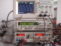
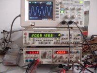
+/-30v
idle current=150mv
offset=0mV
R load=6R
820mV RMS inp.=17V RMS out
48W RMS/6R
A problem uploading images,i must resize all pictures.🙁
Increasing the the value of C8 from 68pf up to 150 pf i can't see any improvement.
Then i tried the opposite.
Decreasing up to 12pf.
Here results.
+/-30v
idle current=150mv
offset=0mV
R load=6R
820mV RMS inp.=17V RMS out
48W RMS/6R
A problem uploading images,i must resize all pictures.🙁
Last edited:
Here
Other test after requirements😉
Other test after requirements😉
Attachments
-
 DSC00009.JPG253.1 KB · Views: 572
 -
 DSC00017.JPG216.9 KB · Views: 186
 -
 DSC00016.JPG217.9 KB · Views: 171
 -
 DSC00015.JPG213.9 KB · Views: 186
 -
 DSC00014.JPG207.3 KB · Views: 183
 -
 DSC00013.JPG212.7 KB · Views: 500
 -
 DSC00012.JPG210.6 KB · Views: 521
 -
 DSC00011.JPG201.6 KB · Views: 545
 -
 DSC00010.JPG200.1 KB · Views: 560
Last edited:
Thimios Great job ...
you changed c4 to 2200uF ? if so, how to look quandradas waves below 1khz
Best Regards
you changed c4 to 2200uF ? if so, how to look quandradas waves below 1khz
Best Regards
Hi all.
I propose a simple opinion:
C1= 1,5uf
R2= 1K
C2= 220pF
R4= 47K
R8= 100R
R9= 2K2
C4= 100uF
I propose a simple opinion:
C1= 1,5uf
R2= 1K
C2= 220pF
R4= 47K
R8= 100R
R9= 2K2
C4= 100uF
Hi all.
I propose a simple opinion:
C1= 1,5uf
R2= 1K
C2= 220pF
R4= 47K
R8= 100R
R9= 2K2
C4= 100uF
Err... no.
OK.
Time constant input filter has to be greater than the time constant of the filter NFB.
C1 x R4 > C4 x R8
1,5 x 47K > 1000uF x 100R
70,5 mseg > 100 mseg.
Gain: 23
Time constant input filter has to be greater than the time constant of the filter NFB.
C1 x R4 > C4 x R8
1,5 x 47K > 1000uF x 100R
70,5 mseg > 100 mseg.
Gain: 23
if the values of c4= 2200uf and R8 = 47R
C1 x R4 > C4 x R8
1,5 x 47K > 2200uF x 47R
70,5 mseg > 103.4 mseg.
Now OK.
C1 x R4 > C4 x R8
1,5 x 47K > 2200uF x 47R
70,5 mseg > 103.4 mseg.
Now OK.
Sorry
Time constant of the filter NFB has to be greater than the time constant of the input filter.
C1 x R4 < C4 x R8
1,5 x 47K < 2200uF x 47R
70,5 mseg < 103.4 mseg.
Now OK.
Time constant of the filter NFB has to be greater than the time constant of the input filter.
C1 x R4 < C4 x R8
1,5 x 47K < 2200uF x 47R
70,5 mseg < 103.4 mseg.
Now OK.
Here
Other test after requirements😉
Thank you Thimios. problem solved. and yes would be interesting to see 100Hz and 50Hz sq waves as Thiago mentions. Once you have done testing Pl post the final values of changed components. I will modify the schematic and post here for benefit of others.
reg
Prasi
This surprised me - congratulations to Thimios, thinking outside the square - I guess the quasi transistor should be slowish, maybe a BD140?
Cheers,
Hugh
Cheers,
Hugh
Why we must use slow transistors?😀This surprised me - congratulations to Thimios, thinking outside the square - I guess the quasi transistor should be slowish, maybe a BD140?
Cheers,
Hugh
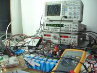
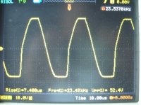
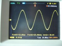
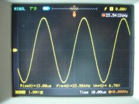
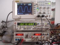
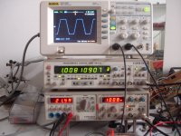
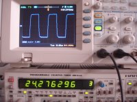
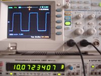
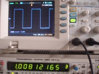
I have a new surprise!
This time C8 position is EMPTY.
To eliminate all gnd issue two channel scope used as floating gnd(Math configuration).
Read amplifier output voltage on voltmeter left on the bottom.
Read test frequency on freq.meter in the center
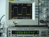
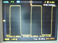
1)just beffore clip(1Khz)
2)soft clip(1Khz)
3)hard clip(1Khz)
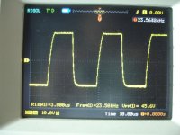
4)soft clip(10Khz)
5)Hard clip(10Khz)
6)Soft clip(20Khz)
7)Hard clip(20Khz)
8)50Khz
9)100Khz
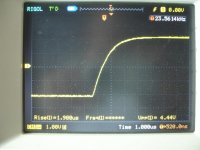
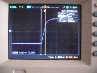
10) Rise time.
To be continued....
Stay tuned!
Attachments
-
 DSC00044.JPG604.4 KB · Views: 197
 -
 DSC00043.JPG535.2 KB · Views: 190
 -
 DSC00042.JPG535.5 KB · Views: 177
 -
 DSC00041.JPG572.8 KB · Views: 170
 -
 DSC00040.JPG560.9 KB · Views: 179
 -
 DSC00039.JPG571.9 KB · Views: 541
 -
 DSC00038.JPG534.9 KB · Views: 561
 -
 DSC00037.JPG548.2 KB · Views: 586
 -
 DSC00036.JPG561.3 KB · Views: 600
 -
 DSC00035.JPG559.5 KB · Views: 644
Last edited:
Thimios,
Hmm, very interesting. Are you using 1381 or BD140 for quasi transistor?
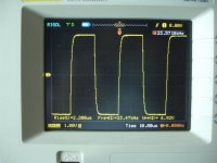
I think this is a perfect square wave at 10KHz, almost perfect.
Not too much slew rate, and slight asymmetry between rise and fall.
It does not use rail voltage too well; I guess the clip is at around 53Vpp? The clip is clean and seems to recover quickly.
NOW, what do you think of the sound quality?
Points to consider:
Bass
Midrange
Treble
Depth and width of image
Sound of trumpets, drums, and violin?
Clarity/Resolution with complex music, eg orchestra
Vocals - natural?
Warm, or cold
Engaging over time, non-fatigueing?
Does it make you tap your foot?
Ciao,
Hugh
Hmm, very interesting. Are you using 1381 or BD140 for quasi transistor?
I think this is a perfect square wave at 10KHz, almost perfect.
Not too much slew rate, and slight asymmetry between rise and fall.
It does not use rail voltage too well; I guess the clip is at around 53Vpp? The clip is clean and seems to recover quickly.
NOW, what do you think of the sound quality?
Points to consider:
Bass
Midrange
Treble
Depth and width of image
Sound of trumpets, drums, and violin?
Clarity/Resolution with complex music, eg orchestra
Vocals - natural?
Warm, or cold
Engaging over time, non-fatigueing?
Does it make you tap your foot?
Ciao,
Hugh
Last edited:
Hi thimios
Congratulations!! All these waveform images are very interesting but even more exciting would be a detailed listening report after you've spent some quality time with your prototype, with your favorite speakers and favorite music.
Regards
Christian
Congratulations!! All these waveform images are very interesting but even more exciting would be a detailed listening report after you've spent some quality time with your prototype, with your favorite speakers and favorite music.
Regards
Christian
Thimios,
Hmm, very interesting. Are you using 1381 or BD140 for quasi transistor?
I think this is a perfect square wave at 10KHz, almost perfect.
Not too much slew rate, and slight asymmetry between rise and fall.
It does not use rail voltage too well; I guess the clip is at around 53Vpp? The clip is clean and seems to recover quickly.
NOW, what do you think of the sound quality?
Points to consider:
Bass
Midrange
Treble
Depth and width of image
Sound of trumpets, drums, and violin?
Clarity/Resolution with complex music, eg orchestra
Vocals - natural?
Warm, or cold
Engaging over time, non-fatigueing?
Does it make you tap your foot?
Ciao,
Hugh
Hugh,i'm using KSA1381EHi thimios
Congratulations!! All these waveform images are very interesting but even more exciting would be a detailed listening report after you've spent some quality time with your prototype, with your favorite speakers and favorite music.
Regards
Christian
I'm using TTC5200 & IRF240 as output.
I want to thank astx who donate me with a lot of parts!
I will post the schematic as built soon.
Ranchu,this need time and a second channel for listening in stereo.
This need more ears too.🙂
Unfortunately i haven't exotic speakers.🙁🙁🙁
I will try to repeat the test using a higher voltage power supply +/-43V.
Last edited:
Thanks Thimios,
Most appreciated; don't worry too much about the speakers - if the amp is good then you will hear it very clearly through midfi speakers. OTOH, bad amps sound bad even with very, very expensive speakers......
Clever of you to find the oscillation was a bad earth. Shows us that grounds are very important, and easily lead us to the wrong conclusion.
Hugh
I must thank you and Ranchu for one more good amplifier in my collection.😉Thanks Thimios,
Most appreciated; don't worry too much about the speakers - if the amp is good then you will hear it very clearly through midfi speakers. OTOH, bad amps sound bad even with very, very expensive speakers......
Clever of you to find the oscillation was a bad earth. Shows us that grounds are very important, and easily lead us to the wrong conclusion.
Hugh
Thanks Prasi,without your pcb never i have try this!
I can't resist to try Thiacomodi pcb too...
Attachments
Last edited:
very simple
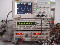
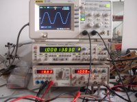
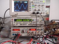
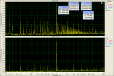
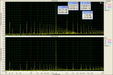
Look at this.
The first picture has been taken without separate input.GND
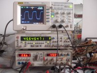
The second picture has been taken connecting the inp GND to star GND.
Listening the amplifier using headphones when nothing connected to inp.i can't hear any hum but i hear hum when inp.connected to sound card out.
Prasi,i believe that this sigleton inp. amplifier need a separate inp gnd to star gnd.😉
Look at this.
The first picture has been taken without separate input.GND
The second picture has been taken connecting the inp GND to star GND.
Listening the amplifier using headphones when nothing connected to inp.i can't hear any hum but i hear hum when inp.connected to sound card out.
Prasi,i believe that this sigleton inp. amplifier need a separate inp gnd to star gnd.😉
Attachments
Last edited:
Look at this.
The first picture has been taken without separate input.GND
The second picture has been taken connecting the inp GND to star GND.
Listening the amplifier using headphones when nothing connected to inp.i can't hear any hum but i hear hum when inp.connected to sound card out.
Prasi,i believe that this sigleton inp. amplifier need a separate inp gnd to star gnd.😉
Thimios, I had the same problem in my VSSA with 10R ground lift resistor. When I shorted that resistor, hum problem went away. could this be the same case here? Just guessing here.
reg
Prasi
Hi guys
I'd like to build a couple of these amps, has a group buy been done for the PCB's? If not are the original designers happy for me to use the board design posted here and get some boards made?
Don't want to upset anyone by taking their designs..... no it's not going to be a commercial operation!
Will the changes being discussed at the moment affect the overall board layout?
Thanks guys, keep up the good work.
Dave
Finally there isn't any problem,this hum was a matter of gnd loop.Look at this.
The first picture has been taken without separate input.GND
The second picture has been taken connecting the inp GND to star GND.
Listening the amplifier using headphones when nothing connected to inp.i can't hear any hum but i hear hum when inp.connected to sound card out.
Prasi,i believe that this sigleton inp. amplifier need a separate inp gnd to star gnd.😉

I spend some time listening Patricia Barber cafe blue.
No original disk not a flac either,just in mp3 from youtube.
I'm surprised from the vocals and crystal clear and strong cymbals.
This simple amplifier have something magic. You must listen to this!

- Home
- Amplifiers
- Solid State
- Very simple quasi complimentary MOSFET amplifier