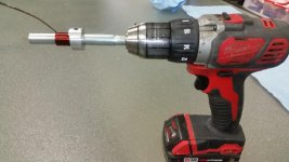
Yep, the way I make them - 12 turns of 1.2mm wire around the 8mm felt pen 😛
That gives me 1.5...2uH and appropriate current rating.
That gives me 1.5...2uH and appropriate current rating.
Yep, the way I make them - 12 turns of 1.2mm wire around the 8mm felt pen 😛
That gives me 1.5...2uH and appropriate current rating.
After maybe the 4th one, I got quite good at it and they looked decent, fingers can get sore after making too many though.
I used enameled 18 ga copper wire about 12 revolutions around a AA battery as a former. 🙂
R29 = 560R now, try to increase the value - make it 680R.
Please test with no load until the bias and the offset are set correctly.
Please test with no load until the bias and the offset are set correctly.
Second channel same problem. Minimum bias lower but still high - >55mV
Both channels sound pretty impressive though.
Both channels sound pretty impressive though.
Second channel same problem. Minimum bias lower but still high - >55mV
Both channels sound pretty impressive though.
Please try to increase R29.
Second channel same problem. Minimum bias lower but still high - >55mV
Both channels sound pretty impressive though.
So what was the problem causing smoking resistors earlier?
So what was the problem causing smoking resistors earlier?
Very high bias at startup.
vzaichenko, R29 is now 680R. Problem solved! 🙂
Thank you!

I figured out an easier way to wind them.😀
Love it!
I do agree that hand-winding is pretty easy, but it would be so much more convenient to be able to buy them ready made. Air core inductors are available and used a lot in RF circuits, but they're all made for itty-bitty currents and not available above 500 nH, which isn't quite enough.
Tom
Very high bias at startup.
vzaichenko, R29 is now 680R. Problem solved! 🙂
Thank you!
What if you take for the bias pot a 200 or a 500 OHM trimpot?
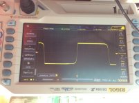
Just been probing the amp with my scope. It looks fine to me but I don't have much experience to know for certain. Can you please look at my picture and see if everything is ok? Thank you.
Sorry, I don't know why the picture is upside down...
Hi Paulo, for 20KHz it looks as expected.
Everything seems to be OK now

What if you take for the bias pot a 200 or a 500 OHM trimpot?
Well, also an option, but you loose accuracy a bit in this case. I prefer increasing R29, simply shifting the trimming threshold. This difference in the value required may be caused by some difference in the parts characteristics. Most likely - the red LEDs used by Paulo are giving a little bit higher reference voltage.
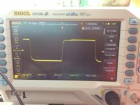
20Khz
Valery,i think is a bit slow
In my tests I had the rise/fall times at the level of 800ns.
However, we don't know the exact parameters of the input signal. Also, some input filter tune-up is possible. I'm keeping it a bit more 'aggressive' just for the sake of repeatability. Also, the values of base-collector caps on the driver's can be tune-up.
However, even with 1.5uS rise/fall time it will sound great.
- Home
- Amplifiers
- Solid State
- IRFP240/9240 Amplifier (simulated on TINA)