Power stress test in stereo
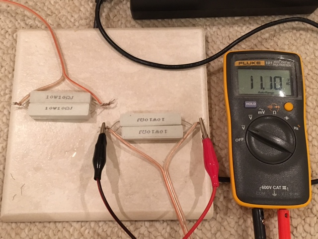
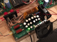
Ok, as promised I hooked up both left and right channels to a 5ohm (10R 10W resistors in parallel for 20w 5R). I was able to get 11.10v before clipping on boh channels so that's 24.6w or about 25w per channel. I had to put some external forced air cooling onto the heatsink for the shunt regulator transistor - it got pretty hot. The power resistors had some moisture in them which started boiling off and pretty soon they were almost starting to smoke. You could smell the heat. The amp itself was fine - I ran it for 20minutes and nothing burned or died. It's actually pretty amazing how much power this little Lunch Money chipamp can put out. If I were to change the resistor network to boost the shunt regulator voltage a bit higher (it's at 17.0v now) maybe 19v or 20v even as the input smps is 24.5v, It can probably do a little more than 25w. I don't have a THD distortion measurement rig yet so who knows how much distortion this is. Just know it can put out power if pressed into it.
Setup with extra fans to keep cool:

Cooking some resistors and clocking in at 25w/ch with 17.0 volt shunt regulated power supply:
Ok, as promised I hooked up both left and right channels to a 5ohm (10R 10W resistors in parallel for 20w 5R). I was able to get 11.10v before clipping on boh channels so that's 24.6w or about 25w per channel. I had to put some external forced air cooling onto the heatsink for the shunt regulator transistor - it got pretty hot. The power resistors had some moisture in them which started boiling off and pretty soon they were almost starting to smoke. You could smell the heat. The amp itself was fine - I ran it for 20minutes and nothing burned or died. It's actually pretty amazing how much power this little Lunch Money chipamp can put out. If I were to change the resistor network to boost the shunt regulator voltage a bit higher (it's at 17.0v now) maybe 19v or 20v even as the input smps is 24.5v, It can probably do a little more than 25w. I don't have a THD distortion measurement rig yet so who knows how much distortion this is. Just know it can put out power if pressed into it.
Setup with extra fans to keep cool:
Cooking some resistors and clocking in at 25w/ch with 17.0 volt shunt regulated power supply:
Attachments

Last edited:
Very cool.
If you used my exact specified parts you'd get 17.8v. Anything beyond 18v presumably causes breakdown of the internals in the chip. 20v is the max where it'll play absolutely fine but with a potentially shorter life span. Beyond 20v it could go at any moment. At least that's how the datasheet reads, and how it's suppose to be. Clearly it's not the definitive picture as you've shown.
You may be experiencing a few things differently than people with the spec'd parts. The KMR section may or may not be operating to full capacity. 😛 Still your test shows us there's no benefit to running 1 channel from 1 chip. You can tie the inputs and outputs however; it might result in very minor smearing, but your application will have more to do with the need for this manoeuvre.
For the record, I once had a chip at 23 volts not knowing it... back before the final design. It sounded wonderful! But who knows for how long...
Last edited:
Oh and are you using a 560R instead of 536R? If you parallel it with a 12k you should get correct voltage.
*Also you could drop the input voltage of an SMPS to 21-22v. They hold pretty steady instead of voltage dropping as much as a linear at 23-24v would do that helps keep the transistor cooler.
The only other person who got so much heat from the transistor (albeit using the correct one, not something else) had it in backwards!
Last edited:
I forget but it's two in series of some sort to get close - maybe 220R and 330R? I recall when I used two 9.1v Zeners in series rather than the TL431 I actually got 18.8v (18.2v + 0.6v) - it worked pretty well that way too.
Thanks for the test. That's over 2 amps current per channel, and I assumed the datasheet was indicating a max of 2 amps current per chip. How much current can the PS provide? Seems like with 50% efficiency it would need to supply 8 amps current???
Again, xrk971, thanks for the experiment. I love this chip!
I may also try the TDA7266M, which appears to be the mono version of the TDA7297. Two of these should run cooler than one TDA7297.
Mike
Again, xrk971, thanks for the experiment. I love this chip!
I may also try the TDA7266M, which appears to be the mono version of the TDA7297. Two of these should run cooler than one TDA7297.
Mike
I was using a 24v (measured at 24.5v) 5 amp SMPS.
25w in a 5ohm load is about 2.24amps from P=i^2 R, i = sqrt(P/R)
11.1v output and input to amp was 17.0v so that is 5.9v drop across the chip's output transistor. P=iv or P=2.24amp x 5.9v=13.2w x 2 channels = 26.4w dissipation.
The shunt regulator dropped 24.5v down to 17.0v or 7.5v drop for P=iv of P=2.24amp x 7.5v = 15w x 2 = 30w dissipated from the shunt transistor (seems about right it was hot and needed the fan).
So total power generated as heat = 50w at load resistors + 26.4w at chipamp + 30w at shunt regulator = 106 watts
Total power capability of SMPS = i V = 5amp x 24v = 120w
So all this makes sense and we were basically at the limit of the PSU. If the shunt regulator had been set to a higher voltage, less would have been burned off as waste in the shunt and more in the load and chip.
These are so cheap, maybe do a test and run them at 20.5v and see - should still be enough headroom for regulator.
Edit: I made a mistake in the analysis for the shunt regulator power dissipation - it is not in series with load and is actually less than the load current as it burns off what is not needed to leave 17v behind. Perhaps the power would be split by the ratio of the voltages so 7.5v/24.5v=30% total and chipamp has 2.24amp for 70% or about 1amp through shunt. So 1amp x 7.5v x 2 = 15watts.
So more like total thermal ouput = 50w at load + 26.4w at amp + 15w at shunt = 91w
Feel free to correct the above analysis if in error... 🙂
Last edited:
Pardon my ignorance...
Do you need to pass a 60 hz signal for your DMM to measure the voltage drop across the
dummy loads?
I still believe these are bridged amps. With no input signal, you should measure approximately 1/2 VCC between each speaker terminal and ground. In your case around 8.5 volts DC. Since both the + and - terminals are at 8.5 volts, you will measure 0 volts across the terminals. Seems that running them in parallel would still give the same DC voltages. What am I missing?
Still a novice.
Mike
According to the factory spec sheet, the output offset is 120mV not 8.5v.
http://www.st.com/content/ccc/resou...df/jcr:content/translations/en.CD00001048.pdf
I did not measure the DC across terminals but seem to recall seeing mV range as the DMM mode dial was going through the different settings to get to ACV.
http://www.st.com/content/ccc/resou...df/jcr:content/translations/en.CD00001048.pdf
I did not measure the DC across terminals but seem to recall seeing mV range as the DMM mode dial was going through the different settings to get to ACV.
Sorry...wasn't clear. With no signal present, if you were to measure DC from ground to the left side of the resistor, you should get around 8.5 volts. Same thing on the right side of the resistor. I thought the difference between the measured voltage and 8.5 was Vos.
Again...I'm still learning!
Oh...my DMM manual stated AC had to be 50 to 60 Hz, but I measured at other frequencies and still got a correct reading. Shouldn't have read the manual!
Again...I'm still learning!
Oh...my DMM manual stated AC had to be 50 to 60 Hz, but I measured at other frequencies and still got a correct reading. Shouldn't have read the manual!
My PSU is capable of far exceeding 5a. The CMC on it is rated at 17a. The advised transformers are 8a or 11a.
Sorry...wasn't clear. With no signal present, if you were to measure DC from ground to the left side of the resistor, you should get around 8.5 volts. Same thing on the right side of the resistor. I thought the difference between the measured voltage and 8.5 was Vos.
Again...I'm still learning!
Oh...my DMM manual stated AC had to be 50 to 60 Hz, but I measured at other frequencies and still got a correct reading. Shouldn't have read the manual!
Maybe Destroyer OS can chime in on what the DC is with no signal input. It may be split at Vcc/2 relative to ground but the measurement is between negative and positive output terminals. In which case I am quite sure it is in the milliV range.
If I used my Folsom PSU which I paired up with an Antek 100VA 15v trafo (22vdc output) I think that is a 4.5amp limit - which appears basically spot on for the max ratings that this amp seems to be putting out with 2.2amps. The spec sheet says 2amps max with 18vdc supply.
The amp has balanced outputs. If you measure DC across the resistor, then that would mean something.
I just measured DC between outputs is 30mV and 8.45v between outputs and power supply ground. But we never connect speakers to ground.
2.24 amps would be your RMS current. Normally that's what we use in power measurements and so on, but to find out what the power supply has to deliver, the average current draw is what we really need.25w in a 5ohm load is about 2.24amps from P=i^2 R, i = sqrt(P/R)
The current draw from a 100% efficient class B amp (outputting a sine wave to the load) looks like what you get from a full-wave rectified sine wave. The average value of a full-wave-rectified sine is (2*Ipeak)/Pi (where Pi is the usual constant, 3.14159....)
Since 2/Pi is about 0.64, this average current is actually a little bit less than the RMS value of a sine wave with the same peak; the RMS value is around 0.71, as I'm sure we all know.
The difference is only a few percent, and probably doesn't matter in practice. (We don't want to push our power supplies right to the limit, and real-world amps draw quiescent current, so the power supply current isn't just a full-wave-rectified sine wave.)
-Gnobuddy
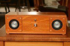
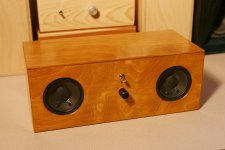
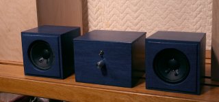
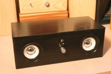
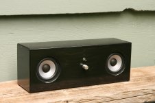
I have been messing around with these little amps and speakers found at thrift stores for a while. I’ve built 12 of them now and having lots of fun. Some of the drivers come from Sony, Technic, Polk Audio, JVC, Cambridge Audio and most recently Paradigm. It’s really amazing how well they perform. Here’s a few of the most recent ones.
The boxes are made of Baltic Birch ply stained and varnished. Hope you like them.
The boxes are made of Baltic Birch ply stained and varnished. Hope you like them.
Attachments

Hope you like them.
Very Nice! What are you using for power supplies?
Mike
I source the DC, 3.5 jacks and switches from DigiKey. They end up costing about 20-25 bucks to build. The sound quality totally amazes me for something this inexpensive
The red one looks nice. Good use for the Chinese version! The little amp really has a grip on speakers but is perfectly friendly to fullrange. I thought about doing something like this but my amp is too large now for something so small.
- Home
- Amplifiers
- Chip Amps
- What the heck? It's less than lunch!