Hi,
I'm new to this community and just started building my owm amplifiers. Not sure whether it is appropriate to ask questions for my first post here, but I'll give this a try.
I have soldered the amplifier and was using sound card FFT to measure the distortion level with software ARTA. I got the 1st chart with only the sound card input cable pluged in and the cable was connected to the DUT, with the DUT powered off. So this is just a reference for me. The overall noise level is about -150db, but with a 50Hz bump at -120db. (BTW, I live in ShangHai China, so the mains are 220V 50Hz) The sound card is ASUS Xonar STX PCIE installed in a desktop PC. Input is single end connection to the output of the amplifier with a 2-resistor voltage divider.
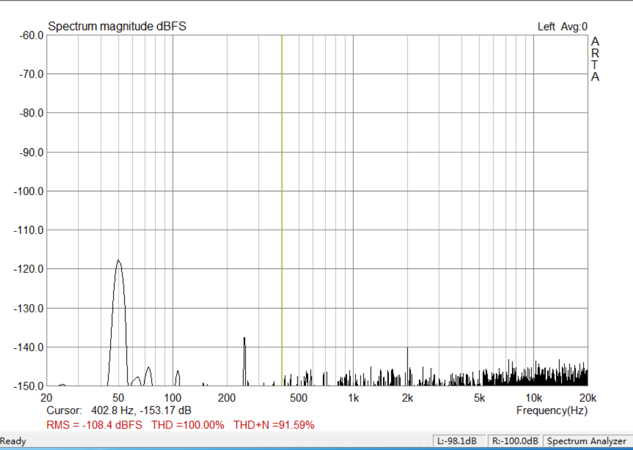
Anyidea how to reduce that 50Hz hum? it is probably OK as the level is low.
However when I turn the DUT on with the DUT input shorted, I got quite some harmonics of 50Hz, 100Hz, 150Hz, 200Hz....all the way up to 20kHz. The amplitude is ~110db. Well, this is my 1st time FFT measurement, so I'm not experienced. Could this be grounding issue or amplifier oscillation or other issues? Can anyone please give me a direction for the trouble shoot? I tried with another amplifier which doesn't have this issue, so I guess grounding isolation won't help (well maybe). I measured the output DC offset is 2mV. Nothing special with a oscilloscope hooked on the output, just noise. Could it be the power supplier?
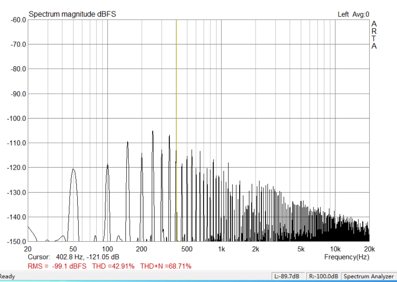
From the chart, it looks pretty horrible, but the amplitude is not high.
Any reply will be highly appreciated.
Thanks!
Richard
I'm new to this community and just started building my owm amplifiers. Not sure whether it is appropriate to ask questions for my first post here, but I'll give this a try.
I have soldered the amplifier and was using sound card FFT to measure the distortion level with software ARTA. I got the 1st chart with only the sound card input cable pluged in and the cable was connected to the DUT, with the DUT powered off. So this is just a reference for me. The overall noise level is about -150db, but with a 50Hz bump at -120db. (BTW, I live in ShangHai China, so the mains are 220V 50Hz) The sound card is ASUS Xonar STX PCIE installed in a desktop PC. Input is single end connection to the output of the amplifier with a 2-resistor voltage divider.
Anyidea how to reduce that 50Hz hum? it is probably OK as the level is low.
However when I turn the DUT on with the DUT input shorted, I got quite some harmonics of 50Hz, 100Hz, 150Hz, 200Hz....all the way up to 20kHz. The amplitude is ~110db. Well, this is my 1st time FFT measurement, so I'm not experienced. Could this be grounding issue or amplifier oscillation or other issues? Can anyone please give me a direction for the trouble shoot? I tried with another amplifier which doesn't have this issue, so I guess grounding isolation won't help (well maybe). I measured the output DC offset is 2mV. Nothing special with a oscilloscope hooked on the output, just noise. Could it be the power supplier?
From the chart, it looks pretty horrible, but the amplitude is not high.
Any reply will be highly appreciated.
Thanks!
Richard
Attachments
Hi, could you please have 1KHz sine wave at the output - set the peak of that 1KHz component to 0db and publish the picture. Then we'll see...
The overall noise level is about -150db, but with a 50Hz bump at -120db. (BTW, I live in ShangHai China, so the mains are 220V 50Hz) The sound card is ASUS Xonar STX PCIE installed in a desktop PC. Input is single end connection to the output of the amplifier with a 2-resistor voltage divider.
Any idea how to reduce that 50Hz hum? it is probably OK as the level is low.
The 50Hz bump is normal when you are connecting both input and output without galvanic isolation. This is the residual of the circuit between the input and output ground through the return paths within the power amplifier. If you connect the input to output directly (using an RCA F-F), you will get a bump that is lower in amplitude, but still not completely gone.
The harmonics are because of the exact same reason. A -105dB noise floor is quite acceptable for a power amplifier and the appearance of the graph ('horrible', as you say) makes it look very bad - but it really isn't so - at least not yet. If you can run a balanced connection you may find some improvement, or some kind of transformer (which introduces its own issues).
Like Valery says, run some actual tests and then we can see what the amp is really doing. If you have similar spiky harmonics in the residual, the performance can be scrutinised. To get decent results out of the Asus cards do not let the output run higher than -3dB, and the input level should not exceed -3dB or the card will introduce its own clipping. This means you need to set your resistive dividers to calibrate your peak (in software) at 0dB or thereabouts.
Last edited:
Hi,
I'm new to this community and just started building my owm amplifiers. Not sure whether it is appropriate to ask questions for my first post here, but I'll give this a try.
I have soldered the amplifier and was using sound card FFT to measure the distortion level with software ARTA. I got the 1st chart with only the sound card input cable pluged in and the cable was connected to the DUT, with the DUT powered off. So this is just a reference for me. The overall noise level is about -150db, but with a 50Hz bump at -120db. (BTW, I live in ShangHai China, so the mains are 220V 50Hz) The sound card is ASUS Xonar STX PCIE installed in a desktop PC. Input is single end connection to the output of the amplifier with a 2-resistor voltage divider.
Anyidea how to reduce that 50Hz hum? it is probably OK as the level is low.
However when I turn the DUT on with the DUT input shorted, I got quite some harmonics of 50Hz, 100Hz, 150Hz, 200Hz....all the way up to 20kHz. The amplitude is ~110db. Well, this is my 1st time FFT measurement, so I'm not experienced. Could this be grounding issue or amplifier oscillation or other issues? Can anyone please give me a direction for the trouble shoot? I tried with another amplifier which doesn't have this issue, so I guess grounding isolation won't help (well maybe). I measured the output DC offset is 2mV. Nothing special with a oscilloscope hooked on the output, just noise. Could it be the power supplier?
From the chart, it looks pretty horrible, but the amplitude is not high.
Any reply will be highly appreciated.
Thanks!
Richard
Lots of high mains harmonics coming from the rectification process which by nature generates harmonic spurs. It certainly looks like you have ground routing issues. Is it possible that the signal ground shares some wiring with the power supply routing, especially to the capacitor (s)?
My view is that you probably want to fix this before looking at the amp performance itself, to avoid erroneous results.
Jan
You also need to calibrate your soundcard measurement. There is no way you could be measuring down to -150db
was about to post that, agree with triplej - the soundcard is likely good for about -110dB, perhaps a bit more best case. so calibrate... be sure to not put too much signal into the front end of the soundcard!! You'll blow it out.
There is a nice thread on the QA400 here that covers some of the input signal conditioning for measurement. Although you can do most of what is needed by the careful choice of a resistive divider, but don't make any mistakes! 😀
_-_-
There is a nice thread on the QA400 here that covers some of the input signal conditioning for measurement. Although you can do most of what is needed by the careful choice of a resistive divider, but don't make any mistakes! 😀
_-_-
You also need to calibrate your soundcard measurement. There is no way you could be measuring down to -150db
Actually, it's not that hard- remember, that's not the noise, it's the noise floor. -150dBFS per bin is not unreasonable for a high resolution measurement. edit: assuming a good 24 bit card
was about to post that, agree with triplej - the soundcard is likely good for about -110dB, perhaps a bit more best case. so calibrate... be sure to not put too much signal into the front end of the soundcard!! You'll blow it out.
There is a nice thread on the QA400 here that covers some of the input signal conditioning for measurement. Although you can do most of what is needed by the careful choice of a resistive divider, but don't make any mistakes! 😀
_-_-
That's one of the the reasons why I asked to show us 1KHz with the peak at 0db - then we will see where the noise floor really is.
For example, here is what I see, measuring one of the amps with a pro-grade card Lynx L22.
Attachments
was about to post that, agree with triplej - the soundcard is likely good for about -110dB, perhaps a bit more best case. so calibrate... be sure to not put too much signal into the front end of the soundcard!! You'll blow it out.
Its better than that. By quite a bit.
ASUS Xonar Essence ST/STX soundcards Measurements | Stereophile.com
Hi Valery,can you post wiring diagram and divider between power amplifier and sound card?That's one of the the reasons why I asked to show us 1KHz with the peak at 0db - then we will see where the noise floor really is.
For example, here is what I see, measuring one of the amps with a pro-grade card Lynx L22.
I have a related question - how can I use a USB sound card to make THD measurements of my amp? I tried making a voltage divider to put the voltage across a dummy resistive load into the inputs. However, I am getting a strange oscillation with the Behringer UCA202. It's a swing to full input (saturates) every 3 seconds. Is this because of some sort of USB power ground loop? If anyone has a link to an amp measuring setup with a USB Sound "card" (dongle) that would be most appreciated.
Thanks,
X
Thanks,
X
What happens when you use a straight loopback? You should anyway to that to establish the baseline.
Hi, could you please have 1KHz sine wave at the output - set the peak of that 1KHz component to 0db and publish the picture. Then we'll see...
Hi Vzaichenk,
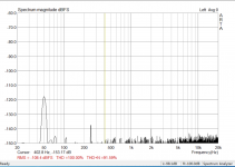
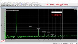
Sorry my response is a bit late due to timezone difference. Here is the proper screen shot when I have this amp drive a 2ohm resistive load with 1kHz 22.5VRMS at the load. So it is outputting 250W.
I didn't use the soundcard output as the signal source and the sig gen of ARTA was switched off to avoid any possible interference. The input signal was provided by an standalone arb. waveform generator at 1KHz. It is a Chinese brand called Hantek HDG2002B, and it probably is not good at all, but should be OK for finding the 50Hz hum issue here. Right?
Thanks!
Richard
Attachments

The 50Hz bump is normal when you are connecting both input and output without galvanic isolation. This is the residual of the circuit between the input and output ground through the return paths within the power amplifier. If you connect the input to output directly (using an RCA F-F), you will get a bump that is lower in amplitude, but still not completely gone.
The harmonics are because of the exact same reason. A -105dB noise floor is quite acceptable for a power amplifier and the appearance of the graph ('horrible', as you say) makes it look very bad - but it really isn't so - at least not yet. If you can run a balanced connection you may find some improvement, or some kind of transformer (which introduces its own issues).
Like Valery says, run some actual tests and then we can see what the amp is really doing. If you have similar spiky harmonics in the residual, the performance can be scrutinised. To get decent results out of the Asus cards do not let the output run higher than -3dB, and the input level should not exceed -3dB or the card will introduce its own clipping. This means you need to set your resistive dividers to calibrate your peak (in software) at 0dB or thereabouts.
Hi sangram,
Thanks for your time looking into this and explain it.
I have the exact transformer on another amplifier (I have 3 mono amplifiers and I just tear one of them down and using the transformers and the case to build a blameless), which doesn't have this issue. So I guess it shouldn't be the transformer, right?
I did the calibration as ARTA user manual described, -3db at the output will drive the input to -2.7db or so. And I'm using ASIO drivers so the windows mixer won't affect the input sensitivity, right?😕 Anyway, I also set the input to 100% at windows mixer. BTW, I'm using Win7 on an intel CPU, 64bit system with UniXornar driver, which according to some posts here is a good stable drivers.
The actual test picture was in my reply post to Valery.
BR,
Richard
Lots of high mains harmonics coming from the rectification process which by nature generates harmonic spurs. It certainly looks like you have ground routing issues. Is it possible that the signal ground shares some wiring with the power supply routing, especially to the capacitor (s)?
My view is that you probably want to fix this before looking at the amp performance itself, to avoid erroneous results.
Jan
Hi Jan,
Thanks for your feedback, and I think so too. Figure out this before making a proper measurement.
I'm pretty sure this is not due to the rectifers. I used the quasimodo (thanks to MGJ on the forum for this great tool!) to settle down the proper snub on the toroidal, and I just did another test with the snub soldered off, the result is the same. Well, could be still the problem, but unlikely, right?
I updated the screen shot with proper scale streching to 0db.
Richard
Attachments

was about to post that, agree with triplej - the soundcard is likely good for about -110dB, perhaps a bit more best case. so calibrate... be sure to not put too much signal into the front end of the soundcard!! You'll blow it out.
There is a nice thread on the QA400 here that covers some of the input signal conditioning for measurement. Although you can do most of what is needed by the careful choice of a resistive divider, but don't make any mistakes! 😀
_-_-
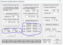
Thanks Bear and triplej for your suggestions. I did the calibration if this is what you meant (I used a Hioki 4281 multimeter to measure the 400Hz output of the sound card, the accuracy should be very high for a Fluke 287 equivelent device and bought for only 2 months):
Also I did an loopback test, this is what I got out of it. I used the right input channel and grounded the left input channel. The cable I made just happen to setup like this, I didn't specifically checked the right and left channel for the 6.25mm TRS jack.
Thanks!
Richard
Attachments
Hi
Your results and methodology should have eliminated the 50Hz hum but it is still present, and the response is quite poor. The numerical results look okay but the graphical results not so great. However an amp that is being pushed so hard may not be the best sounding, nor need to be. When faced with a speaker driven by 250W I would probably have to be picking my brains off the floor rather than distortion from the noise floor.
My 'transformer' comment was aimed at solving your ground loop by inserting a transformer in one of the signal paths to galvanically isolate the input from the output. It seems you have bigger fish to fry right now.
To your actual results, can we see a scope test of the power supply rails with AC coupling on the scope with the same load and signal?
Last edited:
The noise looks like your amp is powered by some switching wall-wart.
It is powered by a properly snubed linear power supplier. 800W transformer with 3x10000uf + 2x2200uf cap per rail, with total 68800uf cap in total.
That is confusing me...😕
BR,
Richard
That's one of the the reasons why I asked to show us 400Hz with the peak at 0db - then we will see where the noise floor really is.
For example, here is what I see, measuring one of the amps with a pro-grade card Lynx L22.
Hi vzaichenko,
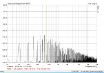
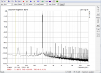
After I replied a couple of post above, it occured to me that you want 0db. I went back to the bench try to get an 0db test, but I failed with the current voltage devider setup. However I managed to get 30V RMS into 2 ohms at 400hz, which is about 450W. Sorry the resistor load is a fixed soldered version too🙁. The input level of the sound card is at -7db, shall this good enough?
I also did a linear average on the chart to make it more accurate. Am I using this correctly?
BR,
Richard
Attachments
Last edited:
- Status
- Not open for further replies.
- Home
- Amplifiers
- Solid State
- Sound card FFT chart on a blameless amplifier