Hi
Your results and methodology should have eliminated the 50Hz hum but it is still present, and the response is quite poor. The numerical results look okay but the graphical results not so great. However an amp that is being pushed so hard may not be the best sounding, nor need to be. When faced with a speaker driven by 250W I would probably have to be picking my brains off the floor rather than distortion from the noise floor.
My 'transformer' comment was aimed at solving your ground loop by inserting a transformer in one of the signal paths to galvanically isolate the input from the output. It seems you have bigger fish to fry right now.
To your actual results, can we see a scope test of the power supply rails with AC coupling on the scope with the same load and signal?
Hi sangram,
Thank you very much for your suggestions!
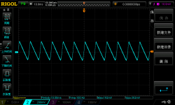
I hooked my Rigol DS1054Z scope to the power supplier (+rail) using the ground spring on the probe to get this result at idle:
The ripple is 100Hz and the ripple Vpp is 352mv. Is it bad for an power amp supplier? I don't have much experience on this.
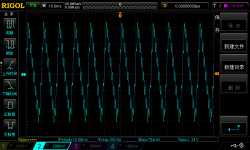
Also, I did the same when have the amp outputting 250W (Vpp is 1.35V):
There is one thing I have to callout here. The amp is a XD blameless which I got from Mr. Self's book with some modifications. The output stage emmiter follower is 0.1ohm, and I used 4 pairs of 3281/1302 biased at 26mv per resistor. Also there is an constant load on the output with 1A load. So the amp at idle consume about 330W (220V main with 1.5A current, which I measured with a Fluke 319 clamp meter). The power transformer is rated at 800W.
BR,
Richard
Attachments
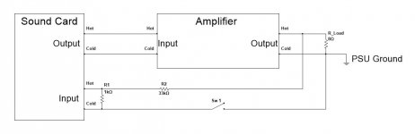
OK guys, here is the way I do it - see attached. Grounding is very important.
In case the amp's input ground is NOT lifted, Sw 1 must stay open. In this case, the only point where the sound card is connected to the amplifier's ground is the input terminal's "Cold" pin.
In case, the amp's input is lifted, Sw 1 must be closed - then the the card is connected to the amplifier's ground at the main PSU ground point.
The divider allows me seeing the spectrums at 20V RMS at the amp's output (the card's internal attenuator is used to fit the scale precisely).
In both cases I have no hum - the noise floor is a straight line just below 120db mark. Both Lynx L22 card and WinAudioMLS software by Dr. Jordan Design are professional products - all the signals are precisely calibrated, giving me full understanding of what's happening.
In case of some other cards and measurement software systems are used - it makes sense to check the input/output volumes with the oscilloscope or True RMS AC volt-meter.
In any case, first of all you have to measure the external analog loop-back - connecting the sound cards input to its output - to see your measurement system's limits and possible artifacts.
After that you can proceed to measuring the amplifiers.
Hope this helps 😉
Cheers,
Valery
Attachments
Also, I did the same when have the amp outputting 250W (Vpp is 1.35V)
Hi Richard
This doesn't look very good.
Here are the issues that need to be examined:
330W is quite high for a 800VA transformer and it will run hot. You can expect surface temperatures of over 65 degrees. Not that it's a problem for the transformer, but good to know.
250mA of idle current per pair is too much for bipolars, you will have severe cross-conduction problems (are having?).
I have few initial observations:
1.3Vpp with a signal output of 22.5V RMS means the power supply ripple is about 35dB below the signal output. The harmonics of 50Hz are also imposed on the PSU output/return at high output levels/currents. Your amp better have decent PSRR - which doesn't look to be the case as of now at least from your graphs. about 70-75dB, which is average but not excellent.
At 250W the PSU is being tasked with 11A RMS, 60kuF seems not sufficient to handle both PSU ripple and this level of output current. If you go by the adage of 10kuF per ampere of output current, you need at least 120kuF.
I am not so familiar with Mr. Self's work but am pretty sure that the 26mV Vre is to be looked at in conjunction with optimal Class B bias, which means your emitter resistors are probably undersized. You are working heavily in Class A and the amplifier is no longer 'Blameless' even if it uses the same circuit. I'll have to hunt down a preview again to confirm though.
Once you sort out the idle performance with (or without) these suggestions, we can look at optimising your performance at higher power. Good Luck!
Mr. Self's work ..... baseline.
(below) is the real "baseline" for a typical "blameless" (with either TPC or TMC)
.... transitional 2 pole feedback compensation.
The amp has input pair noise dominant at low output but drops to <10ppm -100W (2-below).
If you are short of this , it is either layout or the shortcomings of the testing rig.
PS - this was a true test on a 2700 series AP. The forums "Honeybadger" is
pretty much the same circuit as the test amp (EF2 + blameless).
I'm sure a (EF3 +blameless) or Vzaichenko's non-switching EF would halve
these AP tests - especially with more load/wattage.
OS
Attachments
Last edited:
Hi Richard
This doesn't look very good.
Here are the issues that need to be examined:
330W is quite high for a 800VA transformer and it will run hot. You can expect surface temperatures of over 65 degrees. Not that it's a problem for the transformer, but good to know.
250mA of idle current per pair is too much for bipolars, you will have severe cross-conduction problems (are having?).
I have few initial observations:
1.3Vpp with a signal output of 22.5V RMS means the power supply ripple is about 35dB below the signal output. The harmonics of 50Hz are also imposed on the PSU output/return at high output levels/currents. Your amp better have decent PSRR - which doesn't look to be the case as of now at least from your graphs. about 70-75dB, which is average but not excellent.
At 250W the PSU is being tasked with 11A RMS, 60kuF seems not sufficient to handle both PSU ripple and this level of output current. If you go by the adage of 10kuF per ampere of output current, you need at least 120kuF.
I am not so familiar with Mr. Self's work but am pretty sure that the 26mV Vre is to be looked at in conjunction with optimal Class B bias, which means your emitter resistors are probably undersized. You are working heavily in Class A and the amplifier is no longer 'Blameless' even if it uses the same circuit. I'll have to hunt down a preview again to confirm though.
Once you sort out the idle performance with (or without) these suggestions, we can look at optimising your performance at higher power. Good Luck!
Thanks sangram,OS, and Valery for your suggestions. I will do more tests following your leads and report back if there is any progress on this.
I didn't expect so many replies, but really appreciate all of this!
Cheers!
Richard
D.Self states that 0r1 output emitter resistors should use ~ 21.3mVre
Roender states a bit lower @ ~18.5mVre, but his output stage is a triple and includes a CFP for driver.
The absolute maximum continuous DC current draw for your 800VA transformer should be approximately 55% of the AC current rating. It will run hot. Reduce to ~25% for cool operation, especially when the transformer is surrounded by hot heatsinks & high Ta.
I recommend >=20mF per supply rail per amplifier channel for 8ohms speaker.
Double that for 4ohms, i.e. at least ±40mF per channel for 4ohms.
The PSU for a stereo amplifier running two 8ohms speakers from one common PSU would be designed for the equivalent of a 4ohms speaker.
Last edited:
Hi sangram,
Thank you very much for your suggestions!
I hooked my Rigol DS1054Z scope to the power supplier (+rail) using the ground spring on the probe to get this result at idle:

The ripple is 100Hz and the ripple Vpp is 352mv. Is it bad for an power amp supplier? I don't have much experience on this.
Also, I did the same when have the amp outputting 250W (Vpp is 1.35V):

There is one thing I have to callout here. The amp is a XD blameless which I got from Mr. Self's book with some modifications. The output stage emmiter follower is 0.1ohm, and I used 4 pairs of 3281/1302 biased at 26mv per resistor. Also there is an constant load on the output with 1A load. So the amp at idle consume about 330W (220V main with 1.5A current, which I measured with a Fluke 319 clamp meter). The power transformer is rated at 800W.
BR,
Richard
I don't see anything unusual here. Ripple at idle is low and increases with output power. The small additional ripples on the main ripple in the 2nd screen is due to the load from the higher frequency load currents the amp needs. In fact if you count the additional ripples on a 50Hz cycle and multiply with 50Hz you get exactly the signal frequency.
All absolutely as would be expected - I would worry if it was NOT lik it is shown!.
Jan
PS I asume you understand why the ripple is shaped as it is, if not let me know.
I sudpectvSelfs plots are done with a bench power supply - probably regulated. Also, difficult to move from SA to distortion vs freq and cross interpret the results.
If you are getting 1.5 V pk-pk triangle wave on the supply rails there are lots of harmonics. 120'dB down from that would be 1uV on the output. You have little chance of that. A more realistic figure would be 100-200 uV at full power. If you have -100 DB you ain't too shabby.
Getting down to below 100 dB in a practical, real world amp takes some serious effort in layout etc.
The gap between sim and reality is huge
🙂
This is the FFT chart of the power amplifier with the best noise performance on earth.
The Benchmark AHB2, 1W 8 ohm load, measured by Stereophile.

The Benchmark AHB2, 1W 8 ohm load, measured by Stereophile.
For comparison, a power amp with average noise performance, the Pass Labs XA60.5.
An externally hosted image should be here but it was not working when we last tested it.
The Benchmark still has mains harmonics though - probably electric field coupling into some sensitive hi Z nodes. Very good result nonetheless and the result of serious engineering effort.
There are techniques that will allow the designer to suppress PSU noise significantly using feed forward or augmented feedback schemes. I believe Benchmark are doing this.
The Pass labs amp is pretty typical for a low feedback design I'd say. Still a good practical result.
Re SA vs distortion/freq plots: with a straight SA measurement you will be looking across the whole bandwidth for the presence of extraneous signals and the test freq fundamental plus THD.
For the distortion vs freq plots, you look only for harmonics of the test freq. so, you won't see the 50/60 Hz and related harmonics. Trying to correlate directly between the two measurements can be a bit more problematical.
There's no doubt about it, an SA on an amp delivering close to its full output will let you see the whole can of worms. Very tough to get ppm level performsnce on a test like that.
Last edited:
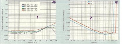
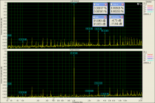
Here is a typical amplifier measurement,nothing special just a 100W RMS published in Elektor No1, Greek version.
The 1st picture is the amplifier on the left channel when a loop(sound card out.to sound card inp.) is on the right channel.
The 1st picture is the amplifier on the left channel when a loop(sound card out.to sound card inp.) is on the right channel.
Attachments
Last edited:
In the previous test 0 db=max amplifier out(when max sound card out) direct to amplifier inp.without any other volume control.I'd rate that amp at -80 dB thimios.
But I think the power levels need to be made clearer.
Used divider=10:1
Last edited:
One thing Boborich's blameless and the Pass Labs XA60.5 in common is the high bias current in the output transistors, which raises the supply ripple even when the amplifier is in idle.
It is good to measure the amp with 2.83Vrms output into 8 ohm load, and plot the FFT chart in the same scale as those from the stereophile's measurement. So you'll know how good your amp is, comparing with the big names in the HiFi industry.
It is good to measure the amp with 2.83Vrms output into 8 ohm load, and plot the FFT chart in the same scale as those from the stereophile's measurement. So you'll know how good your amp is, comparing with the big names in the HiFi industry.
Well this test is as follow.In the previous test 0 db=max amplifier out(when max sound card out) direct to amplifier inp.without any other volume control.
Used divider=10:1
Input voltage=473mV
Out.voltage=16v
Output Divider=10:1
All opinions about measurements procedure welcome!
Last edited:
Compare apples with apples. An amplifier that needs 9.8v input to generate rated power vs 500mV-1V on most other power amps- meaningless comparison. There's 25+dB already.
The AHB2 makes itself look good (its rated specs) by basically having so little gain, the noise is lower by default. Not only that, the long averaging JA performed when testing means random noise (hiss we can hear across the room) is excluded from the pretty little FFT pics.
It's no doubt a respectable amplifier, but to say it has the "best noise performance on earth" is BS. It's been designed to ace the 1 watt THD+N.
Even at is 'highest' sensitivity, is still way lower gain than it should be.
What's next? All line output levels get pushed up to 10v in audiophile gear so we can theoretically get better S/N ratios and our amps essentially become a low gain current buffer?
This is the FFT chart of the power amplifier with the best noise performance on earth.
The Benchmark AHB2, 1W 8 ohm load, measured by Stereophile.
An externally hosted image should be here but it was not working when we last tested it.
I don't see anything unusual here. Ripple at idle is low and increases with output power. The small additional ripples on the main ripple in the 2nd screen is due to the load from the higher frequency load currents the amp needs. In fact if you count the additional ripples on a 50Hz cycle and multiply with 50Hz you get exactly the signal frequency.
All absolutely as would be expected - I would worry if it was NOT lik it is shown!.
Jan
PS I asume you understand why the ripple is shaped as it is, if not let me know.
Hi Jan,
Thanks for your comment! I think I know why the waveform is triangle. It is the result of Cap charge/discharge time difference, the discharge time T =RC, where R is the load, is slower than charge time. Please crooect me if this is not correct.
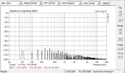
Also I poked around with some trouble shooting, and I found this. I disabled the XD circuit which draws quit some power, now the amp works like a normal blameless circuit. The bias is still at 26mv Vre, and the power comsumption is now 210W. I got this FFT chart on the compuer with nothing attached at idle:
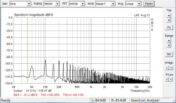
With nothing changed, when I just put the scope probe on the positive rail, I got this on the compuer FFT chart:
Obvirously, the PSSR of my amp is not good at all, right? The noise were injected throught the ground, right?
Any thoughts on this?
Thanks!
Richard
Attachments
For comparison, a power amp with average noise performance, the Pass Labs XA60.5.
An externally hosted image should be here but it was not working when we last tested it.
Hi Banana,
Not sure you would mind if I call you babana, but this is all I have to address you. I'm sorry if this offended you, didn't mean to do so...
Are you saying that the result I got is not bad at all, right? Well this obvirously depand on the accuracy of my test gear. Since I don't have an AP, I won't be able to find this out easily. But I know there is something not right with my build, as I have another amp which doen't have these bumps at the same condition.
BR,
Richard
Hi Jan,
Thanks for your comment! I think I know why the waveform is triangle. It is the result of Cap charge/discharge time difference, the discharge time T =RC, where R is the load, is slower than charge time. Please crooect me if this is not correct.
Also I poked around with some trouble shooting, and I found this. I disabled the XD circuit which draws quit some power, now the amp works like a normal blameless circuit. The bias is still at 26mv Vre, and the power comsumption is now 210W. I got this FFT chart on the compuer with nothing attached at idle:

With nothing changed, when I just put the scope probe on the positive rail, I got this on the compuer FFT chart:

Obvirously, the PSSR of my amp is not good at all, right? The noise were injected throught the ground, right?
Any thoughts on this?
Thanks!
Richard
Sorry, false alarm! This is just due to the ground loop. I'm buying an isolation transformer...
- Status
- Not open for further replies.
- Home
- Amplifiers
- Solid State
- Sound card FFT chart on a blameless amplifier