Thanks for the helpful info, Andrew 🙂
So which way is better ?
I always like the looking of the board with dual sided transistor arrangement, but for the sake of thermal performance, should i follow Valery's board : put all of them on one side ?
Ps : Nice layout Valery.How is the performance compare to the dual sided MT-200 NS-OPS board ?
The big one is actually my layout. I never ran his dual sided layout for long yet, but I ran the first Slewmaster output boards for quite a while. The upper row ran warmer than the lower and the center devices ran warmer than the outside devices, so the center ones in the top row were quite a bit warmer than the outer ones in the bottom row. I don't remember actual measurements, but I do remember the center emitter resistor were flowing more current than the outside when the amp warmed up.
This layout with them all in a single row is working good for me. I haven't physically measured any temperatures yet, just going by feel. They all run fairly even, and current is fairly even through the emitter resistors.
I think part of it depends on how thick the heat spreader is too. A thicker plate will give a more even temperature across its surface. Use a big enough heatsink and none of the devices will get into danger. The thinner the plate and smaller the heatsink the more variation between devices.
Sorry Wilhelm, i missed your mark on NS-OPS board 🙁
My heatsink is 10mm base thick with 50mm fins, and the OPS will run at +-45vdc.Well i think single row transistors is the best for me.For 4 pairs, how much space between each of them is good enough for thermal equality ?
My heatsink is 10mm base thick with 50mm fins, and the OPS will run at +-45vdc.Well i think single row transistors is the best for me.For 4 pairs, how much space between each of them is good enough for thermal equality ?
Last edited:
Could a aluminum or copper clamp compensate some temp difference with a small peltier.
Lähetetty minun H60-L04 laitteesta Tapatalkilla
Lähetetty minun H60-L04 laitteesta Tapatalkilla
Man , I'm so sick of this .
The last slewmaster 5 P just has one gender that is on the top of heatsink.
They run about 2C hotter. this will be countered by NFB.
Those output stages were spaced out to spread the devices equally across a
250mm heatsink.
Intel , I saw your layout ... those closely placed OP's will NOT be thermally
equal. This was the reason I altered my last slewmaster to span the devices
out along the full width of the extrusion.
I keep seeing mentions of "NS-OPS's" and such , these are someone else's
design .... I don't see where this is relevant in this thread ??
believe me , I have learned from any of my present/previous shortcomings.
The "next level" will be groundbreaking , I'm even ditching any analog
power supplies for a 1000W SMPS with smart PFC tech.
All this BS valve front end stuff , along with esoteric TIS's - geez.
Sometimes a good simple 10-14 device circuit will bring all the joy you
could ever ask for.
Now you wonder why I'm not contributing much anymore ?
post #9359 - you see my point ??
OS
Last edited:
For the unequal temperature situation you need good Thermal Stability.Thanks for the helpful info, Andrew 🙂
So which way is better ?
I always like the looking of the board with dual sided transistor arrangement, but for the sake of thermal performance, should i follow Valery's board : put all of them on one side ?......................
Read R.Cordell's interviews.
Last edited:
Man , I'm so sick of this .
The last slewmaster 5 P just has one gender that is on the top of heatsink.
They run about 2C hotter. this will be countered by NFB.
Those output stages were spaced out to spread the devices equally across a
250mm heatsink.
Intel , I saw your layout ... those closely placed OP's will NOT be thermally
equal. This was the reason I altered my last slewmaster to span the devices
out along the full width of the extrusion.
I keep seeing mentions of "NS-OPS's" and such , these are someone else's
design .... I don't see where this is relevant in this thread ??
believe me , I have learned from any of my present/previous shortcomings.
The "next level" will be groundbreaking , I'm even ditching any analog
power supplies for a 1000W SMPS with smart PFC tech.
All this BS valve front end stuff , along with esoteric TIS's - geez.
Sometimes a good simple 10-14 device circuit will bring all the joy you
could ever ask for.
Now you wonder why I'm not contributing much anymore ?
post #9359 - you see my point ??
OS
Pete - sorry, #9359 - my fault.
I saw your temp measurments , with njw0281 , njw302 .Or it's big brother I,m putting together a few slew v3 , I have 150mm * 260mm * 60mm 4pcs . 2 spookys 2 kypton ND v2. I try to fit smd dual for input . Thanks Ostrpper from the bottom of my heart.
Lähetetty minun H60-L04 laitteesta Tapatalkilla
Lähetetty minun H60-L04 laitteesta Tapatalkilla
I keep seeing mentions of "NS-OPS's" and such , these are someone else's
design .... I don't see where this is relevant in this thread ??
believe me , I have learned from any of my present/previous shortcomings.
The "next level" will be groundbreaking , I'm even ditching any analog
power supplies for a 1000W SMPS with smart PFC tech.
OS
It's my bad, OS.
I'm not trying to hijack your thread or promote Valery's OPS.I'm just using it as an example for transistor arrangement.Your contribution to DiyA community is undeniable : many designs, experience, layout....and we all appreciated your works.
Sorry for the misunderstanding that occured bcs of me.
OS: I'm almost 68 and if I've learned anything in life as a designer of homes and buildings is no matter what you design or build someone somewhere is gona take exception, disagree, and try to drag it down. Le Corbusier the famous architect once sighed as tears were streaming down his face at a building dedication close to the end of his life: "The gift of imagination is the gift of the God's imparted to a few who receive innumerable kicks in the a$$ their entire life." Don't let it get you down. I am not an engineer, just a serious audiophile and I for one look forward to your solutions and designs. Ray
Please don't disappear on us Pete!
It has been much too good to quit now. This is one of the few threads that I actually pay attention to.
I expect that more than anything Valery and others were keeping the thread alive waiting for your return.
It has been much too good to quit now. This is one of the few threads that I actually pay attention to.
I expect that more than anything Valery and others were keeping the thread alive waiting for your return.
hello Ostripper, for any change do you have a soft-turn on circuit for a 600VA toroidal
actually for this Antek model AN-6440 600VA 40V 🙂
actually for this Antek model AN-6440 600VA 40V 🙂
Talk to Vzaichenko/Jwilhelm. The "21'st century's" arduino based
soft start is even good on my 1KVA.
It can be timed at 5000mS to charge my 100Kuf cap bank to 90%.
Nothing is ever stressed.
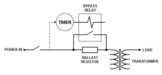
The "21'st" is a 20R ballast resistor bypassed with (2) 20A relays.
It falls into the category of (below 1)
If you are not inclined and want to go cheap - (below 2).
Even as Rod Elliot - Soft-Start Circuit For Power Amps
says NO !! , I have seen the $5000USD Genesis stealth with just 2 20A
NTC thermistors survive 20 years. The NTC's were not even "baked" ,
like in a CRT TV power supply.
Former member MJL21193 also used these NTC's with no issue.
The only downfall might be the NTC flaming with a direct short.
OS
soft start is even good on my 1KVA.
It can be timed at 5000mS to charge my 100Kuf cap bank to 90%.
Nothing is ever stressed.
The "21'st" is a 20R ballast resistor bypassed with (2) 20A relays.
It falls into the category of (below 1)
If you are not inclined and want to go cheap - (below 2).
Even as Rod Elliot - Soft-Start Circuit For Power Amps
says NO !! , I have seen the $5000USD Genesis stealth with just 2 20A
NTC thermistors survive 20 years. The NTC's were not even "baked" ,
like in a CRT TV power supply.
Former member MJL21193 also used these NTC's with no issue.
The only downfall might be the NTC flaming with a direct short.
OS
Attachments
Last edited:
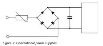
I have a design that I found online a few hours ago but I can not post copyrighted material here,
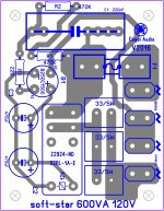
lol so instead of using resistors I can use two NTC thermistors in parallel ? the main where I live is 120V just like in the USA here is the illustration of the PCB maybe I can just use those devices instead or resistors right ?
lol so instead of using resistors I can use two NTC thermistors in parallel ? the main where I live is 120V just like in the USA here is the illustration of the PCB maybe I can just use those devices instead or resistors right ?
Attachments
Last edited:

I have a design that I found online a few hours ago but I can not post copyrighted material here,
lol so instead of using resistors I can use two NTC thermistors in parallel ? the main where I live is 120V just like in the USA here is the illustration of the PCB maybe I can just use those devices instead or resistors right ?
Some just use 1 (15A+). Below .....
That would be the hybrid of the two examples I gave.
OS
Attachments
I have a design that I found online a few hours ago but I can not post copyrighted material here,
lol so instead of using resistors I can use two NTC thermistors in parallel ? the main where I live is 120V just like in the USA here is the illustration of the PCB maybe I can just use those devices instead or resistors right ?
NTC thermistors in Parallel ? There will be current hogging !
NTC thermistors in Parallel ? There will be current hogging !
sorry I'm new to that 😛
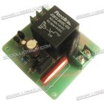
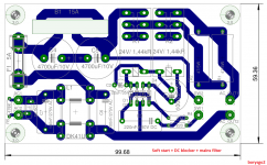
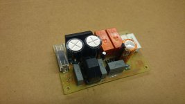
My bit of the off topic too. Bellow my simple soft start (reactance driven). I am using two relays instead of one. Why ?
One of relays works as a on/off switch so on the front panel you do not have to mount a huge hefty not nice looking 10A switch. Threw the front panel SW will be passing only 16mA. On the board there is DC blocker and simple mains filter.
One of relays works as a on/off switch so on the front panel you do not have to mount a huge hefty not nice looking 10A switch. Threw the front panel SW will be passing only 16mA. On the board there is DC blocker and simple mains filter.
Attachments
- Home
- Amplifiers
- Solid State
- Slewmaster - CFA vs. VFA "Rumble"