, not even quasi-comp.
Right, actually the Vas provides pulls down so this architecture has a built-in asymmetry, there's an extra NPN beta in the pull up path. The speed advantage re: the rather bad PNP's available at the time made up for it. Output PNP's were substrate devices (collector conveniently had to be -V) with poor ft's. I find it interesting that unlike valves the study of the work arounds and short-comings of the early planar processes will have little or no value to anyone.
Last edited:
Likely the residual distortion of the AD797 is dominated by effects which a modified compensation scheme would not reduce...
Quite likely but it still seems worthwhile.
..the example is for ~30 dB gain...
The inverter is noise gain of 2 and the integrators are even less.
Not yet sure the consequences of that on distortion reduction, need to do my own sims.
Best wishes
David
The inverter is noise gain of 2 and the integrators are even less.Not yet sure the consequences of that on distortion reduction, need to do my own sims.
I think it's safe to assume that any sort of simulation (using even the best models available to us diyers) are going to correlate poorly with reality at the levels being discussed. Although, it might give decent insight into the loop gain and the control structure. Getting quickly to the "hands dirty" phase, as is expected when discussing < -120 dB effects.
I think it's safe to assume that any sort of simulation...correlate poorly with reality...
I did expect a comment to this effect and it would have been better if I had preempted this in the previous post.
I have already stated that I don't expect accurate distortion results.
But JCX's simulations show impressive correlation with reality, compare his plots with the photos from Scott's AES paper.
So I expect to learn a lot about the loop gain and stability and that tells me the relative improvement possible, even if not an absolute value.
"Hands dirty" once I understand this better, first learn as much as possible from previous work so I don't just repeat it but build on it.
Best wishes
David
"Hands dirty" once I understand this better, first learn as much as possible from previous work so I don't just repeat it but build on it.
Best wishes
David
Not satisfied with the results of others shown here so far? what will your goal be?
THx-RNMarsh
Last edited:
Not satisfied with the results of others shown here so far?...
Certainly satisfied with the performance, I already answered a similar question from Samuel and was happy with his proposed specifications for an excellent but not absolutely state-of-the-art oscillator.
The problem is that a reasonably priced but excellent sweep oscillator is more or less unavailable here.
There's not a lot of second hand quality electronics in Australia, while a weak Aus $ and transport costs make overseas equipment unrealistic.
Samuel's and Davida's oscillator are both still publicly unreleased and won't be cheap or simple when they are.
I am open to ready made solutions if someone has a surplus Tek 505, say.
Plus it's educational to work this stuff out, now I better understand audio amplifiers too.
Best wishes
David
What's your dollar figure. That would most helpful.
I can relate to a poor dollar. When I built my oscillator the Canadian dollar was 1.15CAD/1USD. Since then it has been as low as 0.69CAD/1USD and currently 0.77CAD/1USD. It sucks. I don't want to build anything.
What's your dollar...
Our dollar is about 0.72 US, even less than yours currently. so my limit is pretty low at the moment.
But it's snakes and ladders, the AU$ has been even lower and then moved to above parity with the US$.
I was lucky that when it was low I earned US$ then moved to AU$ as they climbed.
Now I am just reluctant to take a hit on the cross rate.
What's your estimated Can$ price for your oscillator?
Best wishes
David
When I built it, it was about 400USD. That's the PCB loaded and USB control interface. No enclosure or power supply. The PCB is expensive one- off but there are cheaper board houses. It's just a 2.5Vrms source.
I'm working on getting the cost down a bit. Save about $80 CAD.
I'm working on getting the cost down a bit. Save about $80 CAD.
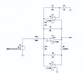
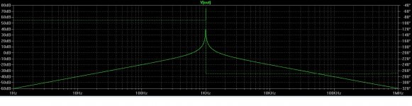
Here is El Cheapo.
It's never been built or tested and you will have to optimize it if you're interested. But it is simpler.
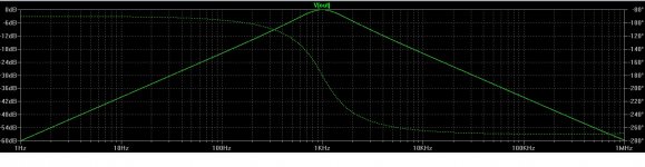
Gives more of a Wien response.
The peak of the filter is at unity and closed loop brings the Q up.
The invertor section would be your multiplier. Just need to control the gain near unity.
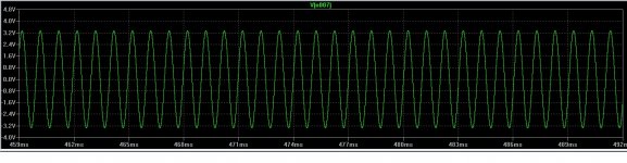
I ran this for one minute with no control and slightly above unity.
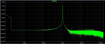
I included spectra. Not that mean anything.
It's never been built or tested and you will have to optimize it if you're interested. But it is simpler.
Gives more of a Wien response.
The peak of the filter is at unity and closed loop brings the Q up.
The invertor section would be your multiplier. Just need to control the gain near unity.
I ran this for one minute with no control and slightly above unity.
I included spectra. Not that mean anything.
Attachments
Last edited:
Certainly satisfied with the performance, I already answered a similar question from Samuel and was happy with his proposed specifications for an excellent but not absolutely state-of-the-art oscillator.
The problem is that a reasonably priced but excellent sweep oscillator is more or less unavailable here.
There's not a lot of second hand quality electronics in Australia, while a weak Aus $ and transport costs make overseas equipment unrealistic.
Samuel's and Davida's oscillator are both still publicly unreleased and won't be cheap or simple when they are.
I am open to ready made solutions if someone has a surplus Tek 505, say.
Plus it's educational to work this stuff out, now I better understand audio amplifiers too.
Best wishes
David
When you say sweepable, do you mean one that has a knob that will sweep continuously over a decade, or does your definition also include one that is switchable within the decade with some degree of granuality, ranging from, say, 11 frequencies per decade to something like the HP339 fine-grained switchable?
Cheers,
Bob
Seems unusual as mask iterations are rather expensive; also many of the distortion effects I see are of rather fundamental nature (e.g. related to available power and basic topology chosen) so not easily improved without drastic changes. But of course almost everything happens in this world; if you can link to a post giving details let us know!
Samuel
Management at most semiconductor companies would agree with you, however the actual numbers tell a different story. A set of reticles are really not that expensive (or as I say, "we've spent more on dumber things") and in my opinion few investments in the semiconductor business have a higher ROI than a set of masks. Maybe the only thing with higher ROI is hiring good people.
Improvements were made to the JFETs on the inputs of the OPA1642 and OPA827 after the initial silicon showed some nonlinear input impedance characteristics. The current parts show excellent performance as I have posted elsewhere. No changes were made to the 211/1611 parts.
There is a difference between the audio and industrial versions of the OPA211 / OPA1611 and OPA140 / OPA1641 other than the fact that the audio versions are not trimmed for offset and drift. The compensation on the audio parts was slightly tweaked to improve THD but with the tradeoff of capacitive load stability being slightly reduced. Really it's just a change in a single cap value.
which could have secondary performance consequences?...other than the fact that the audio versions are not trimmed for offset and drift
I once used the correlation of a particular CMOS op amp's input offset with its DC CM gain linearity to use a cheaper op amp in a pH meter input
by plotting the CM gain error vs individual op amp Vos I saw a very nice parabola - and since the device was offered in a selected low offset grade I was able to meet the instrument's production spec when the op amp data sheet CM gain linearity spec didn't quite make it
I wonder if production trimming for low offset may mask some possible correlation (depending on everything)
which could have secondary performance consequences?
I once used the correlation of a particular CMOS op amp's input offset with its DC CM gain linearity to use a cheaper op amp in a pH meter input
by plotting the CM gain error vs individual op amp Vos I saw a very nice parabola - and since the device was offered in a selected low offset grade I was able to meet the instrument's production spec when the op amp data sheet CM gain linearity spec didn't quite make it
I wonder if production trimming for low offset may mask some possible correlation (depending on everything)
Offset might expose common-mode gain linearity issues that arise from the output impedance of the tail current source. In other words, perhaps mismatch in the input transistors is useful to expose variations in tail current with common mode voltage.
The problem is that a reasonably priced but excellent sweep oscillator is more or less unavailable here.
Best wishes
David
Ok. You really want a sweep osc. I have some schematics for those around somewhere. Is THD secondary to freq sweep?
THx-RNMarsh
Ok. You really want a sweep osc. I have some schematics for those around somewhere. Is THD secondary to freq sweep?
THx-RNMarsh
Here is one of the earliest sweep osc I tried out:
https://www.ssl.berkeley.edu/~mlampton/oscillator.pdf
THx-RNMarsh
Here is one of the earliest sweep osc I tried out:
https://www.ssl.berkeley.edu/~mlampton/oscillator.pdf
Is this a joke?
When you say sweepable, do you mean one that has a knob that will sweep continuously over a decade...
Yes, that is what I had in mind but I plan to do it much like the time base of an oscilloscope.
The idea is to have 12 switched frequencies, each of which can be individually calibrated and optimally trimmed for minimum distortion and noise.
That should provide excellent performance for the spot frequencies needed to check any reasonable amplifier.
Then to have a selectable control that sweeps around that frequency, just like my old CRO.😉
That adds flexibility but is reasonably simple and each sweep does not move too far from optimally trimmed so performance should remain excellent.
I don't actually need sweep over a decade but it is intuitively comfortable.
Similarly I plan to keep a 1,2,5,10,20,50... frequency switch pattern for consistency with my other instruments, even if 50 Hz is a bit problematic to check distortion in a 50 Hz mains power country like Australia.
Because I can always retune a little if I need to.
All seem reasonable?
Ok. You really want a sweep osc. I have some schematics for those around somewhere. Is THD secondary to freq sweep?
No, I want distortion sub PPM, so thanks for the schematic but it's not close.
Best wishes
David
Last edited:
Dave, really good low ppm instrumentation costs big bucks! Only if you have an inside contact with an equipment surplus outlet can you get something like you appear to want at anyway near the price you appear to want to pay. We (Richard, Ed and me for example) BUY our precision test equipment, and we have what you want, but even we would not try to build it.
Richard offered what appeared to be a reasonable solution for you when you complained about your exchange rate, etc. I thought his article was right on target!
Richard offered what appeared to be a reasonable solution for you when you complained about your exchange rate, etc. I thought his article was right on target!
The basic concept in that schematic is still OK and can be made to stay at any freq (hold). But the sine conversion is just an approximation so hardly sub ppm. That portion of the circuit could be improved. But you can use just about any new opamps with very low thd. Perhaps something you have lying around already. But when you said sweepable, I didnt think you meant both sub-ppm and sweep-able. But now you have clarified what you want. Do it cheap though?
You can also start with this topology and tweek the circuitry. http://www.massmind.org/images/www/hobby_elec/e_ckt20.htm
THx-RNMarsh
You can also start with this topology and tweek the circuitry. http://www.massmind.org/images/www/hobby_elec/e_ckt20.htm
THx-RNMarsh
Last edited:
- Home
- Design & Build
- Equipment & Tools
- Low-distortion Audio-range Oscillator