Just let me know the total of the the relay board and selector board. I am in Nashville, TN USA.
Thanks
David
Thanks
David
Just let me know the total of the the relay board and selector board. I am in Nashville, TN USA.
Thanks
David
David, you have PM.
Regards,
Enrico
Hi David,
I still have one board with parts. It's the last one, with a small defect in the PCB that I didn't noticed when I build the board... As you can see it's just a corner but it's better you know.
And I have still few bare boards...
Regards,
Enrico
That's STANDARDS my friend! Way to be picky on behalf of others! FWIW, I would not have groused about receiving that, at all- it's not a functional issue! And, got mine, lookin' great. Just have to figure out all the parts to stuff the rest of it, and a chassis.
I think the smd soldered board needs:
- Two of the three 10 pins connectors
- the selector connector
- the relevant ribbon cables
Does anyone have the exact parts number of the above?
Thanks!!
- Two of the three 10 pins connectors
- the selector connector
- the relevant ribbon cables
Does anyone have the exact parts number of the above?
Thanks!!
Hi Fred,
Tonight I will post here the part numbers that are useful to everybody.
Regards,
Enrico
Tonight I will post here the part numbers that are useful to everybody.
Regards,
Enrico
Here the part numbers:
- Pins connectors - Digikey 3M9460-ND
- IDC ribbon cable - Digikey H3CCH-1006G-ND (other length available)
- Rotary switch - Mouser 611-A20503RNCGE
General info: if you bought the BP board already with SMD parts soldered is not necessary to desolder the input res and caps. Without the 2 original relays they will remain isolated.
Regards,
Enrico
Q1. Would the following cables, connectors suit the purpose?
Ribbon cable, (2 numbers) [link: ]1M-1010-010-3365-012.0-00-AB-00-0 3M Electronic Solutions Division | Mouser
Ribbon connector. 2 numbers [link: ]961210-6404-AR 3M Electronic Solutions Division | Mouser
Q2. The final list of components for a person who is participating in this GB and tfboy’s GB is the following. Please could you call out if there is an error?
C10, C16, C26, C27, C28, C29 - 6 numbers
C12, C13, C14, C15 - 5 numbers
C4, C7, C8, C9,C21, C23, C24, C25 - 10 numbers
Signal Relay - Not needed?
Rotary switch 1
Potentiometer 1
Neutrik male 2 numbers
Neutrik female 12 numbers
Fixed Terminal block 1 ?
JST VHR-3N (Farnell 630482) - 5 numbers
JST (Farnell 630500) - 10 numbers
Q1. Would the following cables, connectors suit the purpose?
Ribbon cable, (2 numbers) [link: ]1M-1010-010-3365-012.0-00-AB-00-0 3M Electronic Solutions Division | Mouser
Ribbon connector. 2 numbers [link: ]961210-6404-AR 3M Electronic Solutions Division | Mouser
Q2. The final list of components for a person who is participating in this GB and tfboy’s GB is the following. Please could you call out if there is an error?
C10, C16, C26, C27, C28, C29 - 6 numbers
C12, C13, C14, C15 - 5 numbers
C4, C7, C8, C9,C21, C23, C24, C25 - 10 numbers
Signal Relay - Not needed?
Rotary switch 1
Potentiometer 1
Neutrik male 2 numbers
Neutrik female 12 numbers
Fixed Terminal block 1 ?
JST VHR-3N (Farnell 630482) - 5 numbers
JST (Farnell 630500) - 10 numbers
Q1 - Yes to both
Q2 - I don't understand on what you are referring. The parts you mention I suppose that are part of tfboy GB, so ask there. The rest of parts in this GB are well mentioned
Dear All,
In this thread http://www.diyaudio.com/forums/analog-line-level/291226-remote-control-bpbp.html Hans Polak propose an interesting integration of the BP preampli with the Maja remote control. He proposed 2 boards:
- VolCB, expressly designed for Maja to manage the Volume and the Input selection
- 4 Input board that, through signal from the VolCB, will switch 4 inputs.
Even if is a clean and well done solution, personally I don't like the solution adopted for the inputs selection, At the end there 6 XLR from the BP + 12 XLR from the Input board to manage 4 inputs, 1 tape line and 1 out.
Anyway, I am thinking to make a small interface board to manage the 6 input board of this GB with the VolCB of Hans having all the futures of Maya and without changing anything in the 6 Input board.
The cost is depending on how many people are interested. The parts are not expensive and as usual the cost of the PCB is defined by the quantities.
The small board that I want to do will be inserted between the input ribbon cable and the relevant connector in the 6 input board.
I will post here the pcb design in the next days.
Best Regards,
Enrico
Interface for the VolCB - Maja Remote Control
I get all the clarification that I need to make the 6 Input board working with the VolCB designed by Hans Polak.
Hans still believe that the best solution should be to change all the relays at 12V to the ones at 5V. In my opinion the solution of a small interface board is still more chip (and easy) if we can realize at least 10 boards. The cost is for the PCB itself, more boards I order and less will be the unit price.
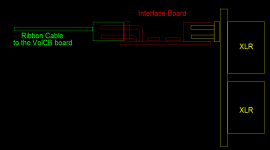
Anyway, attached is a small sketch where you can see (RED) the interface board that, in one side, will be directly connected to the 6 input (YELLOW) with a female 10 pins and in the other side will connect the 10 poles ribbon cable (GREEN). It's the same cable that you already have for the selector board. You need just to cut the connector on the side plan for the selector board and solder directly in the VolCB that already have the pads for the 6 relays. It's very easy and I will post a detailed sketch where you will see the pads.
Please give a look and let me know if you need any clarification.
Best Regards,
Enrico
PS: In the next post I will open the list of people interested to this board
I get all the clarification that I need to make the 6 Input board working with the VolCB designed by Hans Polak.
Hans still believe that the best solution should be to change all the relays at 12V to the ones at 5V. In my opinion the solution of a small interface board is still more chip (and easy) if we can realize at least 10 boards. The cost is for the PCB itself, more boards I order and less will be the unit price.
Anyway, attached is a small sketch where you can see (RED) the interface board that, in one side, will be directly connected to the 6 input (YELLOW) with a female 10 pins and in the other side will connect the 10 poles ribbon cable (GREEN). It's the same cable that you already have for the selector board. You need just to cut the connector on the side plan for the selector board and solder directly in the VolCB that already have the pads for the 6 relays. It's very easy and I will post a detailed sketch where you will see the pads.
Please give a look and let me know if you need any clarification.
Best Regards,
Enrico
PS: In the next post I will open the list of people interested to this board
Attachments
Interface for the VolCB - GB List
Please add your name below with the quantities
emyeuoi - 2
NATBERG - 2
Lbud4 - 2
Please add your name below with the quantities
emyeuoi - 2
NATBERG - 2
Lbud4 - 2
Forget to mention, the boards will be fully populated and tested unless you don't expressly ask for the bare board.
Forget to mention, the boards will be fully populated and tested unless you don't expressly ask for the bare board.
Hi Enrico,
Your interface board looks like a nice and elegant hassle-free solution.
Hans
Hi Enrico,
I´ve sent you a PM with an idea for an alternative for the hex buffer/ULN2003 giving galvanic isolation between Maya and BPBP.
Hans
I´ve sent you a PM with an idea for an alternative for the hex buffer/ULN2003 giving galvanic isolation between Maya and BPBP.
Hans
Hi Hans,
I replied this morning to your PM. I hope you received it.
Tonight when I back home I will post here your nice solution that I fully agreed.
Thanks for your kind support
Best Regards,
Enrico
I replied this morning to your PM. I hope you received it.
Tonight when I back home I will post here your nice solution that I fully agreed.
Thanks for your kind support
Best Regards,
Enrico
Interface with VolCB - Design review
Today I have a nice conversation with Hans about the best technical solution to keep the GND of the BPBP and the 6 input board galvanic separated from the GND of the Maya that, as correctly noted by Hans, normally producing quite some pollution on the supply lines.
So, the agreed solution is to use 6 relays reed that will interface the 12 relays in the 6 input board.
Hans also kindly agreed to add a 8 pin connector in the VolCB for a ribbon cable between the VolCB board and the interface. This will make the interface board a real "plug and play"... Thanks Hans!
The board will be very easy to realize as no SMD parts are more required.
In few days I will post here the picture of the interface board.
This are the components:
1 - Female header 10 pins WURTH - PN 613010243121
6 - Relays reed COTO - PN 9007-05-00
1 - Ribbon cable 8 pin TE - PN 2205070-2. One side of the ribbon cable come with the connector to be soldered directly in the interface board. The other side is to be plugged in the VolCB
They are all through holes so feel free to ask for a bare board or if you prefer I can make and test the board for you.
NATBERG, Lbud4 and pchw please review you choice specifying if you want only "bare board" or leave as it is if you want the boards done and tested.
Regards,
Enrico
- Status
- Not open for further replies.
- Home
- Group Buys
- Bruno Putzeys Preampli - GB for the 6 Input Board