I will have to try mine with a different SMPS. I seem to recall Jason saying he heard something weird with the Connex SMPS as well. Maybe they are worse than others.
It's such an important distinction yet nowhere to be found in the factory spec sheets. Why is that?
It is NOT an important distinction. You don't design based on whether the transistor is lateral or vertical. The spec sheets show the distinction that you need for design...
There are many technologies with vertical. Less with lateral because the industry or the market is for vertical (switching not audio).
Lateral FET has unique (lateral) structure that makes them suitable for audio, which is linear at operating conditions suitable for audio amplifier...
The mosfet you mentioned, I believe it is not lateral from looking at the spec... It is not linear at all!
In general, vertical mosfets have very high transconductance but the capacitance makes them not linear unless you run them at very high current (it is what Nelson Pass is doing with his amps)...
The laterals, OTOH, are very linear (at low current) but the transconductance is very low. The key to lateral design IMO is to get the most out of its low intrinsic transconductance (by designing the perfect drive). And I think there are some new fets from Toshiba that have preferable compromises than the classic K135/J50...
I will have to try mine with a different SMPS. I seem to recall Jason saying he heard something weird with the Connex SMPS as well. Maybe they are worse than others.
My first Connex SMPS was faulty and electrically noisy beyond reason. The replacement performed much better. After some experiences with a few different SMPS, commercially made and sold for audio, I gave up on them and have gone back to good 'ol fashioned linear supplies.
After some experiences with a few different SMPS, commercially made and sold for audio, I gave up on them and have gone back to good 'ol fashioned linear supplies.
Hehe 😀 So many things can go wrong with SMPS (I mean if you can 'hear' the issues)...
Hehe 😀 So many things can go wrong with SMPS (I mean if you can 'hear' the issues)...
Yes, everything is a trade-off. You go for light weight and relatively lower expense but pay for it in performance and internal complexity. Yes, there will be some good SMPS out there. They will be comparatively large and expensive which gives up some of the desirable attributes over a traditional supply.
I do find the SMPSs I have tried are capable of having an effect on the subjective sound quality, and mostly for the worse. Some will prefer the SMPS for their advantages, but to me they make the high end harsher and more fatiguing.
Oh, and some go 'poof' if you look at them funny.
It is NOT an important distinction. You don't design based on whether the transistor is lateral or vertical. The spec sheets show the distinction that you need for design...
There are many technologies with vertical. Less with lateral because the industry or the market is for vertical (switching not audio).
Lateral FET has unique (lateral) structure that makes them suitable for audio, which is linear at operating conditions suitable for audio amplifier...
The mosfet you mentioned, I believe it is not lateral from looking at the spec... It is not linear at all!
In general, vertical mosfets have very high transconductance but the capacitance makes them not linear unless you run them at very high current (it is what Nelson Pass is doing with his amps)...
The laterals, OTOH, are very linear (at low current) but the transconductance is very low. The key to lateral design IMO is to get the most out of its low intrinsic transconductance (by designing the perfect drive). And I think there are some new fets from Toshiba that have preferable compromises than the classic K135/J50...
Please show me what to look for on spec sheet that shows it is a 'lateral FET'? Is it the flatness of the family of curves for the drain current vs drain-source voltage?
Pass indeed runs them hot - always many watts of dissipation. I think the amp I linked from Lineup also runs hot, circa 100w dissipation - yes, total waste of energy but we used to use 100w incadescents all the time before the CFL or LED bulb came along.
It was misleading because both of those threads I linked called them laterals. Don't believe everything you read I guess.
But then again, even verticals can be made to play nice as we have seen with the FH9.

Some will prefer the SMPS for their advantages, but to me they make the high end harsher and more fatiguing.
Yes, that's the point: the advantage is easy for everyone to hear, but the disadvantage is only "audible" to those with sensitive ears.
Please show me what to look for on spec sheet that shows it is a 'lateral FET'?
Will look into the database later (if AndrewT doesn't do it first).
But then again, even verticals can be made to play nice as we have seen with the FH9.
Verticals have high transconductance. This is probably the most important factor for musicality and enjoyment. And everyone can "feel" this...
Linearity (of the laterals) on the other hand, can only be heard by very few people with sensitive ears... and the experience is quite rare because the speaker (as the major contributor to distortion) must not mask this.
There is diy friendly smps schematic in post #10 http://www.diyaudio.com/forums/class-d/182900-class-d-amp-lm566-lm393-2xirf530.html . No need to rewind atx psu transformers.
There is diy friendly smps schematic in post #10 http://www.diyaudio.com/forums/class-d/182900-class-d-amp-lm566-lm393-2xirf530.html . No need to rewind atx psu transformers.
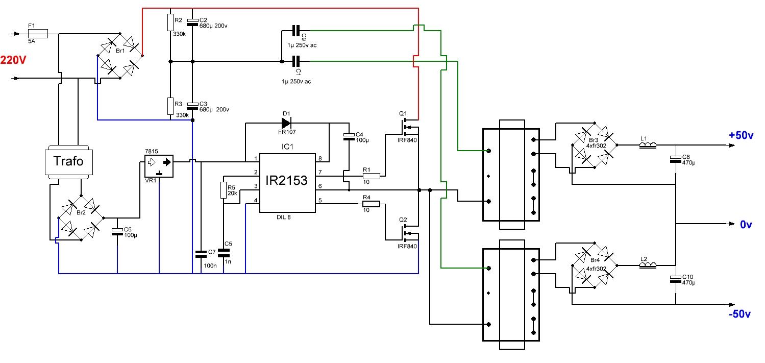
You mean this one? Could you please give more specifics like connections on PC trafo and how to make it work for 110vac input and 35v output? This could be a very handy companion project to go with all Apex amps and might gain some traction around here if the parts are readily available and inexpensive.
Thanks for sharing Apex.
I think that speaker would give a more accurate portrayal of the critical midrange and upper frequencies when comparing different amplifiers.
How about : SB Acoustics SB12MNRX25-04, 4" midrange- 4 ohms
You mean this one?
Doesn't have short circuit protection and over and under voltage protection ?
For DIY that might be essential ?🙂
Or all that is taken care of on the chip ?
You mean this one? Could you please give more specifics like connections on PC trafo and how to make it work for 110vac input and 35v output? This could be a very handy companion project to go with all Apex amps and might gain some traction around here if the parts are readily available and inexpensive.
Thanks for sharing Apex.
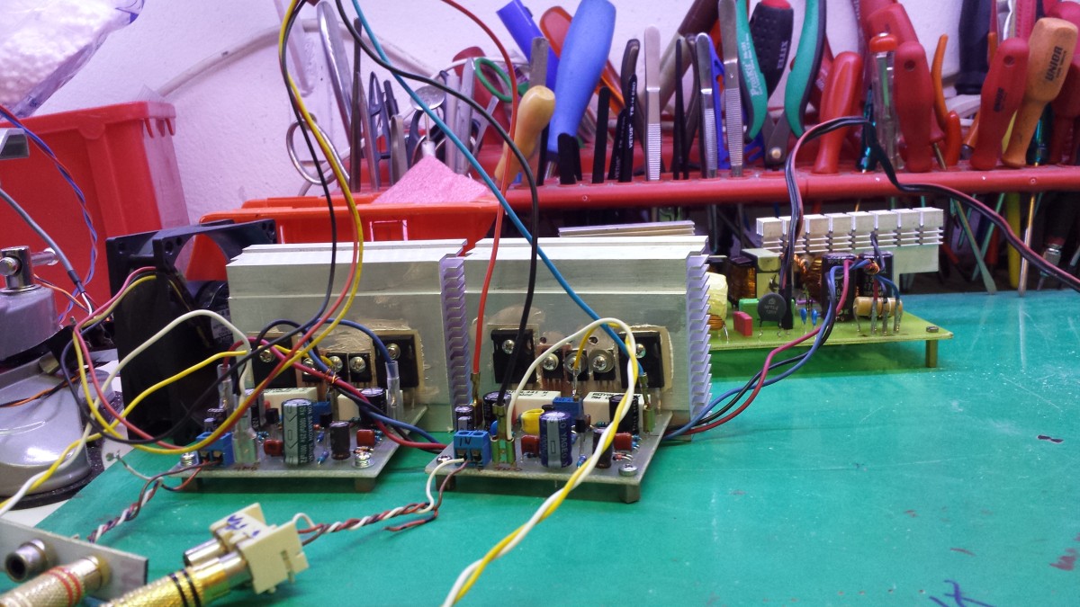
Connection on pc trafo you can see from picture... there is 110v version.
Regards
Attachments
Last edited:
The circuit looks the same for 220 and 110vac inputs - the IR2153 automatically adjusts to maintain 50v out? How do you make it put out +/-35v? I have never taken a standard PC AT power supply apart but do all the switching trafos inside look like this so just follow the pin outs as shown? Does anyone have an illustrative photo?
I have opened up a few PC smps, but I don't understand enough about the control circuits to identify which voltage sends a feedback signal to allow the controller to regulate that particular output.
If the feedback were to be identified correctly and moved to tap into another output one could use an adjuster to send a different proportion of the signal back and end up with an adjustable ~12Vdc output. I believe that most use the very high current %V output as the feedback and control of output voltage.
The next step would be to rewind the transformer to have just two 35Vac windings and use that with a new feedback loop to end up with a regulated ±50Vdc supply.
But I am too afraid to start with a direct to mains circuit where we are banned from discussing or obtaining help from those that know.
The circuit looks the same for 220 and 110vac inputs - the IR2153 automatically adjusts to maintain 50v out? How do you make it put out +/-35v? I have never taken a standard PC AT power supply apart but do all the switching trafos inside look like this so just follow the pin outs as shown? Does anyone have an illustrative photo?
It is not same, on 110vac circuit threre is voltage doubler with Br1, C2 and C3 and you get 310V DC same as 220vac circuit without doubler. This is unregulated PSU without feedback like regular transformer.
I can't see a voltage doubler. They both look the same to me, except for that Mains AC link.
Does that link create a voltage doubler?
Does that link create a voltage doubler?
It is not same, on 110vac circuit threre is voltage doubler with Br1, C2 and C3 and you get 310V DC same as 220vac circuit without doubler. This is unregulated PSU without feedback like regular transformer.
This looks very interesting.
Is there more details available regarding the transformer?
what kind of core, number of turns, etc...
I can't see a voltage doubler. They both look the same to me, except for that Mains AC link.
Does that link create a voltage doubler?
Same trick with voltage doubler:
http://www.diyaudio.com/forums/solid-state/250349-debunker-strong-x4-500-wrms-hi-fi-amp-9.html
- Home
- Amplifiers
- Solid State
- 100W Ultimate Fidelity Amplifier