Agree, but some people don't like class D amps.
I like class Ds 😀
 😛
😛hi apex sir,
can u tell me why the drivers(c5200 and a1943) getting very hot in low volume. i use bd139 schematic. compare with outputs heat the drivers getting very hot.pls help.
can u tell me why the drivers(c5200 and a1943) getting very hot in low volume. i use bd139 schematic. compare with outputs heat the drivers getting very hot.pls help.
What bias current have you got the drivers operating at?hi apex sir,
can u tell me why the drivers(c5200 and a1943) getting very hot in low volume. i use bd139 schematic. compare with outputs heat the drivers getting very hot.pls help.
For a big PA style amplifier one often sees the output devices running at near zero bias current to keep them cool with a too small heatsink.
But that still leaves the drivers running at high quiescent power.
Hi Andrew T !! How can we find the drivers current ? Should we see the volts across R15, 47R 2W resistor ?
Regards
Regards
My new project is dual BA1200 with toridal transformer 80vac-0-80vac 20A
What is the max safe voltage to run Apex BA1200?
How many watt can i except from +/-110VDC from a single Apex BA1200?
What is the max safe voltage to run Apex BA1200?
How many watt can i except from +/-110VDC from a single Apex BA1200?
Last edited:
What bias current have you got the drivers operating at?
For a big PA style amplifier one often sees the output devices running at near zero bias current to keep them cool with a too small heatsink.
But that still leaves the drivers running at high quiescent power.
hi andrew t,
can u tell me how to check bias current for drivers?
You can use this simple DC protection with 40A relay (12V for car)
Does this latch and to reset requires power on and off? How much DC is required before it latches?
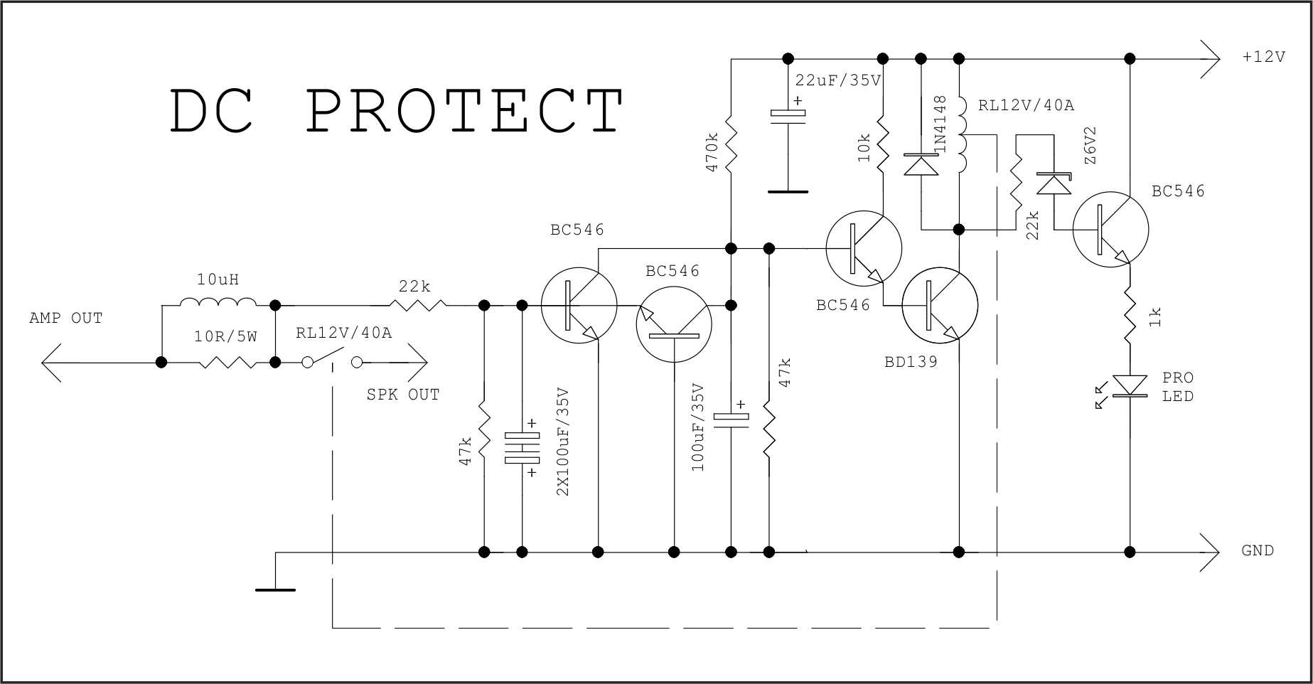
That protect is flawed.
The 10k collector load for the third transistor, bc546, is far too high. It only allows ~1.1mA to flow to the relay driver. The relay driver should be saturated when used as a switch.
The two transistor DC detect has very poor detection of -ve going pulses.
It does not latch.
It does delay self reset due to time required to recharge the 100uF to trigger voltage.
And the last transistor does not need to be a medium power device, many To92 will do that switching duty.
Assuming an Ib=4mA with Vbe=0.7Vbe and Ic=36mA with Vce=0.06Vce
the total driver dissipation is 0.7V*0.004A + 0.06V*0.036A = 0.00496W = ~5mW
The pre-driver has a similar dissipation ~4mW
Why did you attach such a big pic?
Attachments
Last edited:
I only linked the original pic posted by apex earlier in thread. Ok - are there designs you can recommend?
Attachments
Last edited:
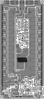
Hi Mister Mile ! I did some improvements on VAS PCB APEX 2000. What should I shoose ? PCB 1 or PCB 2. What do you think ?
Thanks.
Pozdrav
PCB 2, nice work.
Pozdrav
Upload this for homemade procedure🙂Hi Mister Mile ! I did some improvements on VAS PCB APEX 2000. What should I shoose ? PCB 1 or PCB 2. What do you think ?
Thanks.
Pozdrav
- Home
- Amplifiers
- Solid State
- 1000W Simple PA Amplifier