Try it and you will see otherwise....make the measurements , then get back to me...I have done it many times....Otherwise your just arm waiving....
You would not do a full power output measurement.....no core saturation in real life, there is a small gap...
No it is you arm waving when trying to measure something you don't understand. You just have no idea about circuits work and don't even seem to know ELEMENTARY maths and electronics. Not only, your funny theory is basically saying that MAC Intosh patented a circuit without understanding how it works, Crowhurst didn't understand and all the others don't understand. You should get a Nobel price then....
I know how to make a transformer and how it works.You would not do a full power output measurement.....no core saturation in real life, there is a small gap...
You wrote: "remove one tube" hence my comment.If your that concerned about the DC current then disconnect the driver input coupling cap ..this way you kill the AC signal but maintain the DC current..
"If your that concerned about the DC current then disconnect the driver input coupling cap ..this way you kill the AC signal but maintain the DC current.."
That won't work either. Disconnecting the AC drive to one side will only leave the IDLE current nulled. But not the now half wave AC (near class B op) signal put into the xfmr. Half wave rectified. No wonder you are getting only half the meter reading.
I love helping the advertisers here with all the suspense of a who done it novel and the high number of views... but come on already...you don't understand the Mac at all...
The driver tube is Class A and it partially drives the output windings during these test with one tube missing... no half wave rectifier here...
Try doing an analysis or actually doing measurements before shooting from the hip...
Let's keep it friendly guys.
I am waiting for the differential probe measurements....
I'll attempt to measure Va-k and Ik so that we can see the effective load on the tube in the class A and Class B regions. Knowing the turns ratio of the transformer, it should then be blindingly obvious whether the coils are being driven in series, since that will make the load impedance much lighter than if they aren't. Then we'll know for sure if we are allowed to add the voltages from the two coils to compute gain. 😀
I am not sure if I got lost in this long thread but I think you are missing one very important fact in this discussion...
Output tubes see series load, thats is for sure because they drive cathode and anode winding at the same time same as current flowing is given by wire diameter according to current for this load, but since the current flows in opposite direction to plate/cathode the swing is generated only on these sides of tube, and these voltage swings are done by half of the winding and on core they are in parallel way. It creates only one half of the voltage swing on the core but with twice the current thanks to half voltage because of winding orientation. So in fact gear ratio of transformer is low, however the load for tubes is high.
And thanks to huge local feedback together with huge global feedback it can drive incredibly low.
Imagine transformer as simple gearbox, the ratios are strictly given, and you cant count different gears together, they have given ratio you are just changing the torque. Lets say you have power transformer with 100V/2A primary and two secondaries of 50V/1A. When you drive one of the secondaries with 50V/1A, you get 100V on the primary side, just with lower power. When you add second 50V to second secondary you won't get more voltage on primary, just more power.
And the same it is with output transformers, when windings are generating just lower voltage, no matter how many times you connect it there, it does not count voltages together, just power and current counts, voltages and ratios are still same.
Imagine transformer as simple gearbox, the ratios are strictly given, and you cant count different gears together, they have given ratio you are just changing the torque. Lets say you have power transformer with 100V/2A primary and two secondaries of 50V/1A. When you drive one of the secondaries with 50V/1A, you get 100V on the primary side, just with lower power. When you add second 50V to second secondary you won't get more voltage on primary, just more power.
I'm not sure if your response was meant for me. Are you saying you can't connect the two secondaries in series and drive them with 100V and see 100V on the primary?
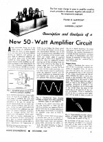
Robert F. Scott describing the basics of the McIntosh unity coupling output circuit:
http://www.pearl-hifi.com/06_Lit_Archive/02_PEARL_Arch/Vol_01/Sec_01/025_Circuits_of_HiFi_Amps.pdf
This paragraph is of particular interest:
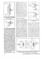
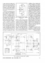
"Each tube now operates as a split-load phase inverter with the power output developed equally in the plate and cathode coils. When the input signal makes the grid of V1 more positive, current flows upward from ground to the cathode of VI and then from its plate through the lower half of the plate winding to B plus. V2 operates in the same manner using the lower half of the cathode winding and the upper half of the plate winding. Since the plate and cathode coils are identical and bifilar-wound with a coupling factor approaching unity, leakage reactance is effectively eliminated and each tube appears to operate through the full primary. The secondary winding sees the two primaries as a single winding so the effective turns ratio can be halved and plate-to-plate impedance reduced to one-quarter the optimum value for the same tubes operating in a conventional push-pull circuit".
That is scenario 2. in my post # 158.
http://www.pearl-hifi.com/06_Lit_Archive/02_PEARL_Arch/Vol_01/Sec_01/025_Circuits_of_HiFi_Amps.pdf
This paragraph is of particular interest:
"Each tube now operates as a split-load phase inverter with the power output developed equally in the plate and cathode coils. When the input signal makes the grid of V1 more positive, current flows upward from ground to the cathode of VI and then from its plate through the lower half of the plate winding to B plus. V2 operates in the same manner using the lower half of the cathode winding and the upper half of the plate winding. Since the plate and cathode coils are identical and bifilar-wound with a coupling factor approaching unity, leakage reactance is effectively eliminated and each tube appears to operate through the full primary. The secondary winding sees the two primaries as a single winding so the effective turns ratio can be halved and plate-to-plate impedance reduced to one-quarter the optimum value for the same tubes operating in a conventional push-pull circuit".
That is scenario 2. in my post # 158.
Last edited by a moderator:
SpreadSpectrum I mean in general not specifically to you. But I can see your point driving it in series, but I was not meaning it like that. I just wanted to say the ratios are given.
But in Mac the transformer core is driven in parallel way with half voltage according to ratios, but tube sees series load.
But in Mac the transformer core is driven in parallel way with half voltage according to ratios, but tube sees series load.
Robert F. Scott describing the basics of the McIntosh unity coupling output circuit:
http://www.pearl-hifi.com/06_Lit_Archive/02_PEARL_Arch/Vol_01/Sec_01/025_Circuits_of_HiFi_Amps.pdf
This paragraph is of particular interest:
"Each tube now operates as a split-load phase inverter with the power output developed equally in the plate and cathode coils. When the input signal makes the grid of V1 more positive, current flows upward from ground to the cathode of VI and then from its plate through the lower half of the plate winding to B plus. V2 operates in the same manner using the lower half of the cathode winding and the upper half of the plate winding. Since the plate and cathode coils are identical and bifilar-wound with a coupling factor approaching unity, leakage reactance is effectively eliminated and each tube appears to operate through the full primary. The secondary winding sees the two primaries as a single winding so the effective turns ratio can be halved and plate-to-plate impedance reduced to one-quarter the optimum value for the same tubes operating in a conventional push-pull circuit".
That is scenario 2. in my post # 158.
If I measure tube currents and voltages and the tube is working into a load that is 1/4 the impedance of a transformer with the equivalent number of turns in series, I'd say I owe some folks here a beer. Plus, I'd have some redesigning of my amp to do. Let's measure some voltages and currents and calculate the load impedance.
Here's the original Frank McIntosh and Gordon Gow paper; turns out it wasn't in an Audio Anthology after all.
Attachments
-
 Frame001.jpg501.7 KB · Views: 190
 -
 Frame002.jpg488.5 KB · Views: 200
 -
 Frame003.jpg470.3 KB · Views: 192
 -
 Frame004.jpg513.5 KB · Views: 188
 -
 Frame005.jpg500.8 KB · Views: 133
 -
 Frame006.jpg573.9 KB · Views: 72
 -
 Frame007.jpg627 KB · Views: 68
 -
 Frame008.jpg630.3 KB · Views: 71
 -
 Frame009.jpg636.7 KB · Views: 70
SpreadSpectrum I mean in general not specifically to you. But I can see your point driving it in series, but I was not meaning it like that. I just wanted to say the ratios are given.
But in Mac the transformer core is driven in parallel way with half voltage according to ratios, but tube sees series load.
Yes, I agree with everything you say there.
The windings are driven in series and there is the same amount of voltage developed at the plate and the cathode (i.e. 2x cathode or anode voltage) while the driver is developing the cathode voltage + bias. Hence the voltage gain is almost 2 (being the bias much lower than the cathode voltage). The transformer ratio has nothing to do with this: this is about the power tube gain.I am not sure if I got lost in this long thread but I think you are missing one very important fact in this discussion...
Output tubes see series load, thats is for sure because they drive cathode and anode winding at the same time same as current flowing is given by wire diameter according to current for this load, but since the current flows in opposite direction to plate/cathode the swing is generated only on these sides of tube, and these voltage swings are done by half of the winding and on core they are in parallel way. It creates only one half of the voltage swing on the core but with twice the current thanks to half voltage because of winding orientation. So in fact gear ratio of transformer is low, however the load for tubes is high.
In a true cathode follower all the voltage will be developed at the cathode and the driver has to develop all of it. Hence the voltage gain is (about) 1.
I have already done the maths twice. I won't do it again.
I am not sure what this means.And thanks to huge local feedback together with huge global feedback it can drive incredibly low.
When you have both driven in series, it will 50+50V but also the step-down ratio be 2x as well hence the secondary voltage will the same and the current will be 2x. This however has nothing to do with the gain of power tube because such a gain is the ratio of its output voltage at the primary and its input.Imagine transformer as simple gearbox, the ratios are strictly given, and you cant count different gears together, they have given ratio you are just changing the torque. Lets say you have power transformer with 100V/2A primary and two secondaries of 50V/1A. When you drive one of the secondaries with 50V/1A, you get 100V on the primary side, just with lower power. When you add second 50V to second secondary you won't get more voltage on primary, just more power.
Here's the original Frank McIntosh and Gordon Gow paper; turns out it wasn't in an Audio Anthology after all.
Thanks Chris; I provided the link for that article in post #25 😀
45:
by 2 voltage gain you mean when you put 10V on grid1 you can see 20V on plate and 20V on cathode, or you mean that 20V distributed between cathode and plate as result of 10V+10V and thats that gain of two?
by 2 voltage gain you mean when you put 10V on grid1 you can see 20V on plate and 20V on cathode, or you mean that 20V distributed between cathode and plate as result of 10V+10V and thats that gain of two?
45:
by 2 voltage gain you mean when you put 10V on grid1 you can see 20V on plate and 20V on cathode, or you mean that 20V distributed between cathode and plate as result of 10V+10V and thats that gain of two?
The second. In reality a bit less than 2 because of the bias. So 10V + small bias on the grid and 10+10V cathode + anode. That's a gain of almost 2. In the cathode follower which is unity gain 20V output means (a bit more than) 20V input. That's (almost) gain = 1.
The stage is rather heavy loaded (2k3) so the gain drops to some 1.5.
This is not different from a standard cathodyne phase splitter.
This is not different from a standard cathodyne phase splitter.
Last edited by a moderator:
45: Yes, thats is logical and correct. Good point.
From electrical point of view. But if we assume the output stage as one complex including all windings, than this gain of 2 is used to make possible parallel connection of windings and in final creates no gain at all, right? So from different point of view the whole final stage gain is 1. I mean in gear ratio thinking or how to say it.
From electrical point of view. But if we assume the output stage as one complex including all windings, than this gain of 2 is used to make possible parallel connection of windings and in final creates no gain at all, right? So from different point of view the whole final stage gain is 1. I mean in gear ratio thinking or how to say it.
45: Yes, thats is logical and correct. Good point.
From electrical point of view. But if we assume the output stage as one complex including all windings, than this gain of 2 is used to make possible parallel connection of windings and in final creates no gain at all, right? So from different point of view the whole final stage gain is 1. I mean in gear ratio thinking or how to say it.
If the primary windings are driven in series they cannot magically go in parallel. What you are trying to transform is just the step ratio.
- Status
- Not open for further replies.
- Home
- Amplifiers
- Tubes / Valves
- McIntosh bifilar output stage test proof