Lookie here..I found the lady we can ask who makes the trafos at mac
She's winding some quad balanced power transformers. She's been there for decades..She may not know the circuit but she can wind some bifilar OPTs for us for a 150 a pop...Ya think? LOL
https://www.youtube.com/watch?v=uoU3ff7FY2s
She's winding some quad balanced power transformers. She's been there for decades..She may not know the circuit but she can wind some bifilar OPTs for us for a 150 a pop...Ya think? LOL
https://www.youtube.com/watch?v=uoU3ff7FY2s
This is true in the case of Doc Hoyer and the other gentleman that posted that winds mac iron...My only question is,why do the people wind the mac opt transformers say the circuit is unity gain..
Winding transformers is a very practical thing. You can take a good transformer open it, replicate it. It's all about practice to get a good one and you can become very good at it. However it doesn't imply one understands how a transformer works and it doesn't mean one understands how circuits work.
....He gave us pretty logical reasons why you can't treat this as a cathodyne and the only reason I tend to trust these guys is because of their talent in winding these.
I can't see any logical reason. Sorry!
What is gain? It is simply the ratio of the output signal to the input signal. The input signal in this case is easy to define. It is the difference in AC voltage at the grids of the two output tubes.
The output voltage requires a bit more thought to define. Some here are defining that output voltage as the AC voltage on the bifilar winding (obviously the two windings have a DC offset of hundreds of volts). If you define the output voltage this way, the stage does indeed have a gain of a little less than one. I won't argue with that, but I will argue that it is a poor choice to define the output voltage this way.
I think it makes much more sense to define the output voltage as the sum of the AC voltages on both of the coils, even though they are tightly-coupled coils wound in parallel, because they are being driven in series. This allows you to correctly predict the load that the tubes see and it allows you to just take your numbers over to tube characteristics and do a proper job of designing the output stage. Think about it for a second: How can I draw a proper load line on tube characteristics if I assume that the output voltage is half of the change in Va-k? It muddles all of the thinking up. It makes much more sense from an amplifier design point of view to define the change in Va-k as the output voltage.
But I can see why a transformer designer might be tempted to say that the output voltage is just the AC voltage across the bifilar winding. The problem is that this creates problems for you when you try to design an amplifier that can only be solved by thinking about it as an output stage with mu of 2.
My only question is,why do the people wind the mac opt transformers say the circuit is unity gain..
Have you tried asking him to draw a load line for an MC275 on some KT88 characteristics? I'd be interested to see what he comes up with.
The only way I can really see verification in this is to treat the output stage by itself and take measurements with a dif probe.
We want to see what the output stage does by itself,irrespective of the influence of the 12BH7 and 12AX7. One thing we do know,even if there voltage gain in the output which is entirely possible,it isn't nearly as much as it is in a conventional output stage given the comparative measurement shown at the output in the ST70..
We want to see what the output stage does by itself,irrespective of the influence of the 12BH7 and 12AX7. One thing we do know,even if there voltage gain in the output which is entirely possible,it isn't nearly as much as it is in a conventional output stage given the comparative measurement shown at the output in the ST70..
I don't totally agree
[
Winding transformers is a very practical thing. You can take a good transformer open it, replicate it. It's all about practice to get a good one and you can become very good at it. However it doesn't imply one understands how a transformer works and it doesn't mean one understands how circuits work.
Many people have tried to wind Mcintosh OPT transformers and can't do it but can reverse engineer most other kinds..Heyboer is one of the best winders I know of and I took an Mc225 to him and he couldn't do it. I have also used Maine transformer and they do almost every type transformer but guess which ones they can't do?
McIntosh
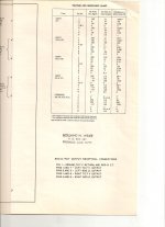
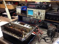
Tonight we had our session measuring the MC275.
The amplifier was fed with a 400 Hz signal.
Voltage at the 8 ohm loudspeaker output terminals was 2,66 VRMS.
This is a little under 1 watt of output power; the loudspeaker terminal was actually loaded with a 9 ohm resistance (the 8 ohm tap is actually 9 ohm to have the same load wrt the 4 and 16 ohm taps).
Then we measured the AC voltages at the grids of the KT88 power tubes; this was done referenced to ground.
At both grids the AC voltage was 15,5 VRMS.
Then measurement of the AC voltages at the plates and cathodes of both KT88's; all four values the same at 11,7 VRMS.
The output transformer has a step down ratio at the 9 ohm tap of 16:1, the load impedance of the output stage therefore is 16² x 9 = 2k3.
When we calculate back from the loudspeaker terminal, the total push-pull output swing of the KT88's must be 2,66 x 16 = 42,56 VRMS.
We measured the plate and cathode voltage swings already to be 11,7 VRMS each; the total output swing of the tubes therefore is 4 x 11,7 = 46,8 VRMS.
This is slightly higher than the value of 42,56 VRMS; this difference is the insertion (copper) loss in the output transformer (0,8 dB in this case).
So to get 46,8 VRMS out of the pair of KT88 tubes there was 2 x 15,5 VRMS = 31 VRMS at their two grids.
The voltage gain of this output stage therefore is 46,8 : 31 = 1,51.
This confirmed my measurements a couple of years ago: the output stage behaves as a composite cathodyne phase splitter with a maximum theoretical gain of 2 in case of being unloaded. Because of the 2k3 load impedance the real voltage gain is 1,51.
So yes, there is voltage gain in the output stage.
My friend is well documented with MacIntosh manuals; below you see the voltage and resistance chart as printed on the MC275 manual; look at the AC Volts at rated output.
The values on this chart confirm our measurements:
KT88 pin 5 (grid) 149V; pins 3 and 8 (plate and cathode) both 116V.
So the same voltage gain of a little over 1,5 (2x116 : 149).
Attachments
Last edited by a moderator:
[
Winding transformers is a very practical thing. You can take a good transformer open it, replicate it. It's all about practice to get a good one and you can become very good at it. However it doesn't imply one understands how a transformer works and it doesn't mean one understands how circuits work.
Many people have tried to wind Mcintosh OPT transformers and can't do it but can reverse engineer most other kinds..Heyboer is one of the best winders I know of and I took an Mc225 to him and he couldn't do it. I have also used Maine transformer and they do almost every type transformer but guess which ones they can't do?
McIntosh
Not to be arrogant but I can, and as in the good old MacIntosh days by using high quality c-cores.
Not to be arrogant but I can, and as in the good old MacIntosh days by using high quality c-cores.
It appears you are correct about being arrogant...However, your assumptions are incorrect, I highly doubt you wound any Mac outputs... they wouldn't work as originally intended with your assumptions... The measurements are OK but incomplete..
First problem is you need a way of verifying the PHASES of your measurements.. If you verify the phasing of the waveforms in the windings sections you would see they could not ever add up the way you added them up...scope the waveforms with diff probes with respect to each other see the phasing.. If you truly knew the number of turns in the original transformers you would not have made the assumptions you made..
Bi-Filar windings do not SUM...they are in PARALLEL...
You feed in a 31V diff grid signal into this stage and you get a 23.4V Diff signal across the each of the paralleled windings... (.869 x .869) x 31V = 23.4V ... The only thing that SUMS is the 2 plate sections that are in SERIES, which is 11.7V + 11.7V .... The CATAHODE sections also SUM the same way as well..
Both PLATE and CATHODE Bi-Filar windings are in Parallel and in Phase and centered taped with respect the GND...
This is stage gain of approx. .75 ...
Last edited:
The bifilar windings are: cathode of tube 1 and plate of tube 2, then the other bifilar winding is cathode of tube 2 and plate of tube 1.
Just sum the cathode and plate AC voltages for one tube (the magnitudes), then divide by one AC grid voltage. Gain 1.5
If there is no load OR if the tube has infinite gm, the gain goes to 2.
Same as a Circlotron, which it is EQUIVALENT to.
Just sum the cathode and plate AC voltages for one tube (the magnitudes), then divide by one AC grid voltage. Gain 1.5
If there is no load OR if the tube has infinite gm, the gain goes to 2.
Same as a Circlotron, which it is EQUIVALENT to.
Last edited:
I am surprised by the controversy, and agree with SpreadSpectrum, smoking-amp, 45, Pieter, et al. about the gain and equivalent impedance.
There is nothing magic about the Mc transformer, either. The C-core may deter some winders, but it is certainly possible to get an acceptable (for DIY purposes) EI-core with two parallel-wound primaries. There are maybe some stock Lundahls that could be used in a UC connection with good results, too.
There is nothing magic about the Mc transformer, either. The C-core may deter some winders, but it is certainly possible to get an acceptable (for DIY purposes) EI-core with two parallel-wound primaries. There are maybe some stock Lundahls that could be used in a UC connection with good results, too.
It appears you are correct about being arrogant...However, your assumptions are incorrect, I highly doubt you wound any Mac outputs... they wouldn't work as originally intended with your assumptions... The measurements are OK but incomplete..
First problem is you need a way of verifying the PHASES of your measurements.. If you verify the phasing of the waveforms in the windings sections you would see they could not ever add up the way you added them up...scope the waveforms with diff probes with respect to each other see the phasing.. If you truly knew the number of turns in the original transformers you would not have made the assumptions you made..
Bi-Filar windings do not SUM...they are in PARALLEL...
You feed in a 31V diff grid signal into this stage and you get a 23.4V Diff signal across the each of the paralleled windings... (.869 x .869) x 31V = 23.4V ... The only thing that SUMS is the 2 plate sections that are in SERIES, which is 11.7V + 11.7V .... The CATAHODE sections also SUM the same way as well..
Both PLATE and CATHODE Bi-Filar windings are in Parallel and in Phase and centered taped with respect the GND...
This is stage gain of approx. .75 ...
I did tell Pieter to post photos to we can see exactly how it was done at least that's what I always believe you should do but what it's worth Chris,your analysis concurs with Dennis Hoyers who is the official Mac rewinder if you call McIntosh or Audio Classics and being you two are the only two I know of that wind the Mac output trafos, at least in the US,I don't find surprising you came up with the same results.
What "should" end this controversy is that the PRIMARY to SECONDARY turn ratio is EXACTLY 8 when using the 9 Ohm tap...
So explain to me how the #### you get a gain of 2 with a turns ratio at 8 ????
Also keep in mind this amp is practically in Class B ... very cold AB1..
Since one tube spends "almost" half of it's time in cut-off ... The AC signal currents could not SUM in series due to the cut-off valve, but instead flow back to its single source valve though the Center-Tap ... On the Cathode winding the AC current signal path is Center-Tap right to chassis GROUND.. On the Plate side it goes through Center-Tap and through decoupling filter cap then to GROUND... This is 1/4 of the winding section..
Last edited:
What are you calling the primary? Just the plate winding?
The primary is the sum of the plate and cathode windings. Nothing mysterious there, just the AC ground point is now in the middle of the primary instead of at one end for conventional P-P.
The primary is the sum of the plate and cathode windings. Nothing mysterious there, just the AC ground point is now in the middle of the primary instead of at one end for conventional P-P.
What are you calling the primary? Just the plate winding?
The primary is the sum of the plate and cathode windings. Nothing mysterious there, just the AC ground point is now in the middle of the primary instead of at one end for conventional P-P.
Once again... the Plate and cathode winding are Bi-Filar wound and in Phase and electrically in parallel...
Yes.. The SUM of the Plate and cathode winding in this measurement posted is 11.7V + 11.7V ... which sums to 23.4V ....
You can't SUM two windings that are electrically tied to GROUND with respect to both their center points... look at the phasing...
I am surprised by the controversy, and agree with SpreadSpectrum, smoking-amp, 45, Pieter, et al. about the gain and equivalent impedance.
There is nothing magic about the Mc transformer, either. The C-core may deter some winders, but it is certainly possible to get an acceptable (for DIY purposes) EI-core with two parallel-wound primaries. There are maybe some stock Lundahls that could be used in a UC connection with good results, too.
There are a lot of people that say they can wind the mac OPT but went put to the task they can't do it.I suppose if they were trained to do it they could but I have taken a Mc225 over to Phil at Heyboer and then I sent it to Maine transformer and both said we can't do it..If there is someone that will do it and do it right in the 450 dollar range,let me know and I will give them a try..It's a just a spare one have being I have a lot of mac tube amps but I would love to have this spare because the writing on it is perfect.I'm in hurry so they can take their time.
AH-Ha! That's where you are going wrong. The windings are in series for each tube. The OTHER tube is then in parallel with it, but plate and cathode reversed.
Check back to post 58 for the equivalence to the Circlotron.
In terms of the bifilar pairs: Each tube has one wire from each bifilar pair, and they are connected in series. (there is no parallel connection between plate and cathode windings for a given tube)
Check back to post 58 for the equivalence to the Circlotron.
In terms of the bifilar pairs: Each tube has one wire from each bifilar pair, and they are connected in series. (there is no parallel connection between plate and cathode windings for a given tube)
Last edited:
AH-Ha! That's where you are going wrong. The windings are in series for each tube. The OTHER tube is then in parallel with it, but plate and cathode reversed.
Check back to post 58 for the equivalence to the Circlotron.
OK... real simple way to end this drama...
Remember this quote from the measurement team:
"When we calculate back from the loudspeaker terminal, the total push-pull output swing of the KT88's must be 2,66 x 16 = 42,56 VRMS.
We measured the plate and cathode voltage swings already to be 11,7 VRMS each; the total output swing of the tubes therefore is 4 x 11,7 = 46,8 VRMS"
OK.. I would like to see this 46.8V RMS actually measured against your 31V grid to grid input..and not speculated as you did in your quote...
I bet you can't measure this 46.8V RMS .... because it's not a real voltage..
The windings don't sum.. if they did SUM you would be able to measure this fictitious 46.8V ...that would prove your Gain = 2 theory...
Last edited:
Of course they sum, just measure AC across plate to cathode for a given tube. (DC removed, just put a 1 uF cap in series with the meter)
With equal AC voltages to ground for both the cathode and plate windings, they must either sum to twice that or sum to zero. (depending on phase) Zero would give zero gain!
With equal AC voltages to ground for both the cathode and plate windings, they must either sum to twice that or sum to zero. (depending on phase) Zero would give zero gain!
Last edited:
Of course they sum, just measure AC across plate to cathode for a given tube. (DC removed, just put a 1 uF cap in series with the meter)
Yes.. I agree...
That a 1/2 winding CATHODE will sum with a 1/2 winding PLATE ...
Your back to .75 GAIN by doing this..
But a full CATHODE winding and full PLATE winding do not SUM....because they are Grounded in their Centers... Thus the Thevenin equivalent puts the windings in PARALLEL with respect to their Center-Taps..
- Status
- Not open for further replies.
- Home
- Amplifiers
- Tubes / Valves
- McIntosh bifilar output stage test proof