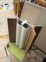
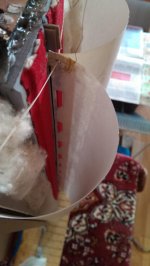
Here you cand see both of them. One version with elastics is my second version and has round 8 shape cilinders and the other hasnt got the elastics, its been sustained only on both cilinders pushing force and hinges, has "butterfly" shape as yours, and triangles wich radiates hights outside the rigid portion of the cilinders. This second version has way better hights and cleaner mids but its somehow limited to 1khz.. strange thing..
Attachments
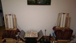
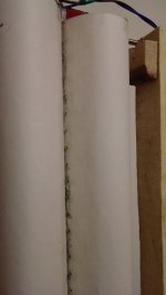

I tested this type of "butterfly" roundness for the cilinders in my last config (forgot to report about) and found that this configuration adds some more hights. The 8 shape dampens abit the hights.. will show you some pics in my next post with the top view from my stereo pair of rubans wich waits silently for the mic tests.
only thing i noticed with the butterfly is that the rest of the cylinder acts more like a hinge instead of part of the membrane, it wil result i worse lower end anc changes of more resonances. 🙁 at elast thats what i noticed
only thing i noticed with the butterfly is that the rest of the cylinder acts more like a hinge instead of part of the membrane, it wil result i worse lower end anc changes of more resonances. 🙁 at elast thats what i noticed
Hi Sergiu and Wrine
Glad to have found new and passionate collaborators like you ! To be honest the french thread on cine et son has'nt mutch interest since its quite inactive for a couple of years and even more . I tried to reactivate it few monthes ago and only got dummy responses that look more like some attempt to kill the thread ... As you will read there, there has been a real war arround this speaker in europe and it is possible that some actual constructors don't apreciate that people like us can make and even improve the speaker that they sell several thousands dollars.
i will invite both of you of course and we can try to wake up this french thread .
Concerning what you call the "butterfly" shape, my goal was just to fold te 4 papers close to the bobin as the front and rear edge of it stay straight and the bobin keep a perfectly plane shape in the middle of the gap. It works ! even in my island where humidity varies from 100 to 20% sometimes.
Before this i tried lots of antimoisturizing stuffs that didnt work but made the membrane heavier and shortened the highs response.
I use a printed circuit board bobin (Cu) that i ordered in china looking exactly like DEMINIERES one 2X10turns (10 on each side ) in series connexion. i tried the parallel but it has less efficiency on my configuration :
200hz low pass Filter 12db for the bass 2X38CMEminence boomers each side
200hz hi pass filter 12db for the janus .
I don't have a very accurate way of measurement (SynArta prog on my laptop) but it looks likethe bass response is good no hole arrond the 200Hz, the trebbles are here but they begin to roll off at 10000 what does'nt disturb me very mutch but they would certainly need to be improved for a younger listener ! 😉 what i'm actually looking for before trying to add an additional ribbon supertweeter.
may be you shoud try the butterfly shape with elastics and not triangles that probably shorten the bass response ...
efficiency is more than 97db (boomers) because i need to attenuate them at least 3 db.
Attachments


Hi tubegeek,
Nice setup you have there. Congratulations!
If they (from cine et son) are against people like us than i would not want to go there. Better stay here. I like when lots of ideas and thoughts come together and emerges in something good but i dont like argues and fights...
My last attempt of Janus had the triangles sticked to the metal and had awfull bass response and i have losen all the triangles out. Now the membrane is sustained by top and bottom hinges and the triangles are now laquered and radiating hights outside the cilinders. Tomorrow or wednesday i hope to measure them so that i can make some newer versions with another type of cuts in a new membrane. 😉
I just listened today to the triangle version with my wife in full range mode and was impressed. They dont seem to bother coupled like this. They play very well in the full range combination at 10w. Interesting..
As Wrine sayed, the butterfly version is limiting the wekened bass (i had the last version runing throught a first order 300hz filter), and the rest of the membrane is acting like a huge hinge. Thats why when i try to round the cilinders abit with my hands the speakers shows some bass frecv. It really makes sense now.
When i bypass the filter, the speaker plays clearly in fullrange mode. Interesting. Tomorrow i will crank up the vollume abit to see how it dampens the resonances.. 😀
Cheers
Sergiu
Hi Sergiu,
we have the same goals about this speaker and i'm glad to have found a place again where passionate people can friendly share informations about their works on the Janus speaker .
May i ask you a question ? i've seen your photos and videos on you tube and it looks like you test your speaker without the lateral "V baffles" that are very important for the lower response.
Another thing about the hights response : i don't understand clearly what you say about the triangles about it . you made the lose by unsticking them from the metal but now they are lacquered and imporve the hights ? how ?
Did you try to add a V paper in the center between the 2 cylinders from bottom to top, like the additional cone that we see on the broadband round speakers ? if yes tell me if it's worth to improve the hights response and what you think about it .
Hi Sergiu,
we have the same goals about this speaker and i'm glad to have found a place again where passionate people can friendly share informations about their works on the Janus speaker .
Me too.
May i ask you a question ? i've seen your photos and videos on you tube and it looks like you test your speaker without the lateral "V baffles" that are very important for the lower response.
I dont consider the V shape yet relevant. Someone said on cin et son that these V shapes are there to improve spatiality and 3d imaging and he was right. I havent measure it yet but tested this aspect. Subjectively speaking from the listening tests that i conducted with my wife and a friend of ours who is in a band (trompet singer) it seems that if round V shape (i havent tested the flat V shape yet) is used this really improved the imaging, 3d, and added some weight to the mids and made them more profound, and the bass a litle bit more round when playing full range. I will add this feature at the end on the final version, when all the things are settled and tested.
Another thing about the hights response : i don't understand clearly what you say about the triangles about it . you made the lose by unsticking them from the metal but now they are lacquered and imporve the hights ? how ?
Wrine and I have agreed, and seen allot of reality examples where laquer was used in the past on the paper membrane on old fashion paper dome tweeters.
Wrine and I have tested and concluded that if you add concentrated laqueur on 20% to 30% of the membrane (from the active portion where the cilinders meet to outside of the cilinders) you really improve hight frecv, and if you add more, nasty resonances appear because mids tend to be improven too much if more laqueur is aded. In my next post i will show you more detailed pics about my triangles..
Did you try to add a V paper in the center between the 2 cylinders from bottom to top, like the additional cone that we see on the broadband round speakers ? if yes tell me if it's worth to improve the hights response and what you think about it .
I will add this V shape on the top and bottom at the end of our journey. Till then i have to measure first the quantity of hights that are coming from inside the cilinders.
Cheers
Sergiu
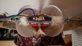
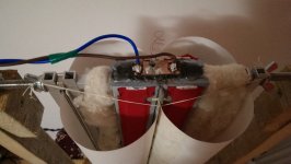
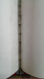
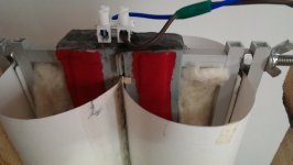
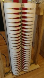
Here in the first pic you can see the triangles made from V shape cuts that are laquered on each side (you cannot see them laquered from the pics, but they are) and coming out of the rigid portion of the cilinders.
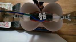
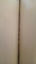
In the second pic you can see the hinges that i use instead of the classic elastics.
Cheers
Sergiu
In the second pic you can see the hinges that i use instead of the classic elastics.
Cheers
Sergiu
Attachments
Here we are Wrine,
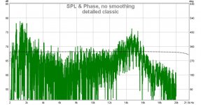
Please help me interpret these results. Or anyone who knows how to interpret the results.
Thanks in advance.
Sergiu
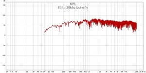
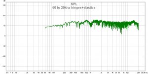
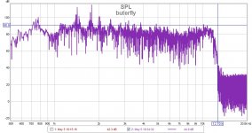
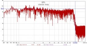
Ps: I forgot to tell that the output level on both variants is 2v @1000hz for the elastics variant (8 ohms) and 1.4v for the butterfly (4ohms) as measured. The JLH 69 cant do more, and i dont know why its only 0.5W output power..
Please help me interpret these results. Or anyone who knows how to interpret the results.
Thanks in advance.
Sergiu
Ps: I forgot to tell that the output level on both variants is 2v @1000hz for the elastics variant (8 ohms) and 1.4v for the butterfly (4ohms) as measured. The JLH 69 cant do more, and i dont know why its only 0.5W output power..
Attachments
Last edited:
The last 2 ate freq response as i mentioned Shark teeth. The butterfly does smooth it more but you can serie does Not reach 20khz
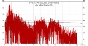
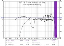
Oh i see iTS Not phase but you scale is 50 db 🙂 haha of course it looks almost flat with such huge scale 🙂 try 5 db or 10
Thank you very much. Here are the 10dB scale.
Where did you figured from that i dont reach 20khz? Please explain. Its way tooo much to learn in this measurement segment from the web...
Thank you very much.
Cheers
Sergiu
Where did you figured from that i dont reach 20khz? Please explain. Its way tooo much to learn in this measurement segment from the web...
Thank you very much.
Cheers
Sergiu
Attachments
Thank you very much. Here are the 10dB scale.
Where did you figured from that i dont reach 20khz? Please explain. Its way tooo much to learn in this measurement segment from the web...
Thank you very much.
Cheers
Sergiu
oh still looks rahter flat to be honest.. what was the distance ?. could you try Holmimpulse ? since rew is harder to read somehow , and is maybe more comparable with my measurements from in the past.
btw is you mic calibrated ?
here i i made a crude measurement with and without back cylinders 🙂 just to see what happens, i used a aluminium single coil of only 1.5 ohm
green is with backside, red without. i somehow always have this drop at 500hz not sure what it is. it might be something to do with dimensions. Since your version if waaay bigger mine is only 20cm. you can see that removing the back does 2 things.
One it removes the dip at 1.6 Khz , and it removes weight so the highs extend a bit more.
Attachments

Last edited:
Thank you Wrine,
First i calibrated the internal sound processor (line in to headphones through a short 20cm wire to make a loop).
Then i played a 1khz sound through the amp and adjusted it to gain 2.8v but i obtained no more than 2v in 8ohms as i said.
After that i introduced the official calibration file from the Behringer site and after that i recalibrated the mic (finetuning) from the program used.
After this i measured exactly 1meter from the center of the ruban, and oriented the mic exactly in half the lenght of the speaker (i oriented the mic exactly to the center) and exactly at 1 meter distance.
Now i'm at a funeral, but after this i will analise again the graphs because i seen that the program also generated an impulse and i found those graphs also and will post them soon.
Cheers
Sergiu
Ps: thanks in advance Wrine.
I see good results at your versions also Wrine. Maybe those dips of your version could be from the smaller size.
Cheers
Sergiu
Cheers
Sergiu
Hi Wrine,
You are right. In thos first measurement i havent entered in the program the claibration file from the mic. Now its all set: audio+mic.
Your are right; with these two i havent touch neither the 15khz. Its a healthy 12.8khz at max...But we have to note a very important aspect: the hights are not impressed by added mass like i left those triangles outside. The secret lies in the total amount o material removed from the active portion (the coil).
What do you say now about the measurements? Classic way seems smoother?
I will try tomorrow to remove the triangles and then see the new results. It should remove, theoretically a huge amount of mass..
How can i interpret the SPL and phase graphs? Can you explain?
Thanks in advance.
Cheers
Sergiu
Attachments

oh still looks rahter flat to be honest.. what was the distance ?. could you try Holmimpulse ? since rew is harder to read somehow , and is maybe more comparable with my measurements from in the past.
btw is you mic calibrated ?
here i i made a crude measurement with and without back cylinders 🙂 just to see what happens, i used a aluminium single coil of only 1.5 ohm
green is with backside, red without. i somehow always have this drop at 500hz not sure what it is. it might be something to do with dimensions. Since your version if waaay bigger mine is only 20cm. you can see that removing the back does 2 things.
One it removes the dip at 1.6 Khz , and it removes weight so the highs extend a bit more.
Hi Wrine,
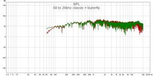
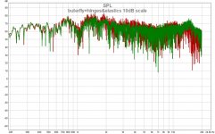
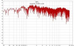
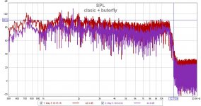
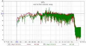
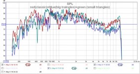
And here it is. The complete graph. Yesterday i tested from 150hz to 20khz. Look Wrine red is classic, with elastics and hinges and green is the butterfly.
What do you say? I know that it sucks at hight frecv, now i can really see it, but its almost there at the bass chapter. Am i right?
These measurements are taken from 1 m at 2v output and a 66uF /150v cap in a first order filter arrangement for 300hz .
Cheers
Sergiu
Attachments
Last edited:
Hello Wrine, my friend,
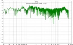
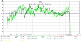
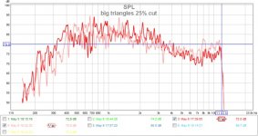
Here are some new measurements. The very interesting thing is that it really matters if you deflect the inside of the cilinders; it really helps where the front collapses.
Bellow are the graphs. The crisper paint is outside the cils and the faded paint is inside the cils.
The last pic is with all the three arrangemets.
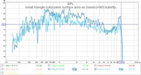
With the big triangles i removed 25% of one face of th ruban but still no signs of higher frecv response.. The "classic way" has about 11% cutted but has rectangular cuts. The smaller cuts has also abot 11% cuted but in a triangular way.
I measured the inside of the cilinders at exactly 30cm distance from the top of the cilinders with the mic pointed exactly at the coil (inside).
What did you do Wrine to go so close to 20khz? Please tell me your secret.
Cheers
Sergiu
Here are some new measurements. The very interesting thing is that it really matters if you deflect the inside of the cilinders; it really helps where the front collapses.
Bellow are the graphs. The crisper paint is outside the cils and the faded paint is inside the cils.
The last pic is with all the three arrangemets.
With the big triangles i removed 25% of one face of th ruban but still no signs of higher frecv response.. The "classic way" has about 11% cutted but has rectangular cuts. The smaller cuts has also abot 11% cuted but in a triangular way.
I measured the inside of the cilinders at exactly 30cm distance from the top of the cilinders with the mic pointed exactly at the coil (inside).
What did you do Wrine to go so close to 20khz? Please tell me your secret.
Cheers
Sergiu
Attachments
Last edited:
- Home
- Loudspeakers
- Planars & Exotics
- A DIY Ribbon Speaker of a different Kind