I wanted to start up a thread about another LADSPA plugin that I am thinking of writing. The plugin would implement a Linkwitz Transform, the type typically used to boost bass response of a woofer/subwoofer. In addition, it would incorporate a feature that will reduce the boost (the LF gain) dynamically in response to the signal if/when the output level is boosted to a high enough level to cause digital clipping. The gain reduction would be implemented with some amount of lookahead to smooth out and reduce the perceived effect of the boost reduction.
The concept is related to, but not exactly the same as, a clipper/limiter. It's very well suited to a boosted-bass application such as the LT or any kind of low-frequency boosting filter (e.g. 1st or 2nd order shelf filter). Instead of operating in the time domain, peak reduction is done in the frequency domain by dynamically adjusting the LT transfer function. The underlying assumption is that the high gain at low frequencies is primarily responsible for the high signal levels, so reducing the gain there will bring the signal back into an acceptable range. This is different from a limiter, because there is no guarantee that the signal will be maintained within a given threshold value. A hard limiter could be placed next in the signal chain if that behavior was desired, or perhaps limiting or wideband gain reduction could be written into the plugin as optional features.
Control action similar to this has existed in the past but implemented with analog circuits. In a sense the proposed plugin is a bit like a dynamic "loudness" control (but for the low bass only). A loudness control was a feature found on some preamps in the 1980s and 1990s (e.g. from Yamaha and others) and was based on the Fletcher-Munson equal-loudness curve. An analog implementation of boost-limiting for a closed-box subwoofer (but using a double integrator instead of the more flexible LT) was patented by Long and Wickersham and (I believe) used in Bag-End's ELF line (see: Method and Apparatus for Operating a Loudspeaker Below Resonance Frequency - US Patent 4,481,662). For details, see the paragraph in the lower half of column 5, on page 6 of the patent.
Using DSP, a lookahead buffer can make the onset of the gain reduction more gentle and make the effect more transparent sonically. Because it is operating in the frequency domain, the problems associated with limiting should (based on my prior SPICE modeling) be mostly eliminated, and adding a lookahead should make this even more so.
I don't recall seeing this kind of DSP processing tool anywhere before. If you know of one, especially firsthand, I would be interested to learn about how well it functions. In general, comments about my approach are very welcome!
Is there any interest in this kind of functionality for the DSP toolbox?
Last edited:
Hi, Charlie...
Sounds like a worthwhile project, though not on my wish list (plenty of headroom). My wishlist includes a volume-based "loudness" compensation. Amount user-configurable. I often listen a low-levels, and some compensation would be wonderful....
Sounds like a worthwhile project, though not on my wish list (plenty of headroom). My wishlist includes a volume-based "loudness" compensation. Amount user-configurable. I often listen a low-levels, and some compensation would be wonderful....
Hi, Charlie...
Sounds like a worthwhile project, though not on my wish list (plenty of headroom). My wishlist includes a volume-based "loudness" compensation. Amount user-configurable. I often listen a low-levels, and some compensation would be wonderful....
In general, time-varying of an IIR filter can have some serious pitfalls. Because a filter has a phase response as well as amplitude response, varying one of the filter parameters (like corner frequency) too quickly can cause audible intermodulation distortion because the phase behavior of the filter (and therefore it's delay curve) is also being modulated. This is one problem that I need to keep in mind for the plugin I describe above. It isn't such a huge problem if the signal is strongly bandlimited like we have for a subwoofer application, especially if followed by fixed lowpass filters. But if you wanted to do dynamic IIR filtering on the full audio spectrum you have to do some "tricks" like multiband processing in order to keep the artifacts sufficiently suppressed.
So, with that in mind... if you envisioned a plugin that was varying the amount of "loudness control" automatically as a function of signal level with a time response on the order of 100msec or less, then you are probably out of luck. If, on the other hand, you want something with a fixed amount of contour for each "loudness" setting then this is feasible. You could study the curves in this Yamaha manual excerpt:
An externally hosted image should be here but it was not working when we last tested it.
and come up with several sets of LADSPA filters that approximate each curve and then manually implement them (all together in an ecp file, in the input signal path) and switch between sets of filters when you want to change your master volume level.
.
Actually, I was thinking more of a longer time constant filter, something on the order of seconds. I don't really want it adjusting from program dynamic range, but more for my listening level. I suspect that would be much more complex.
That's the one thing I miss from having a knob to turn.... back when I had a pre-amp in circuit.
That's the one thing I miss from having a knob to turn.... back when I had a pre-amp in circuit.
Actually, I was thinking more of a longer time constant filter, something on the order of seconds. I don't really want it adjusting from program dynamic range, but more for my listening level. I suspect that would be much more complex.
That's the one thing I miss from having a knob to turn.... back when I had a pre-amp in circuit.
If you want to drive an automatic adjustment of the state of the filter(s) that make up the "loudness" curve, you can do it slowly (e.g. over seconds). So, yes, that's possible.
Not sure if you are aware of it, but you can use MIDI control to change LADSPA filter parameters in ecasound. You might be able to do it that way instead of in code. It's not clear to me how this works internally, in the filter, however...
I've done a little reading and a brief lit search (via whatever I could find online). There are several ways that one can try to implement a time-varying filter, but some of these can lead to instability problems (or can't guarantee that there won't be instability). There is some good background reading on this topic here in section 3.5.4: "Transient Elimination Methods for Time-Varying Recursive Filters":
http://users.spa.aalto.fi/vpv/publications/vesan_vaitos/ch3_pt4_transients.pdf
It looks like the safest approach is to calculate multiple LTI filters in parallel and then cross-fade between them. I know that the LT changes both magnitude AND phase. Perhaps I could simply calculate the output of the fully LT'd signal, and another signal that has no amplitude change but has the phase change of the full LT (via an allpass). I might then be able to crossfade between them (e.g. like an analog mixer would) without artifacts or distortion. I will think about this approach a little more and do some modeling of the signals to see if I think this can really work.
Another similar approach is to crossfade between LT outputs from LT filters that have only slightly different amounts of boost, however, I would need to continually calculate quite a number of these at the same time and then crossfade between them. Because the phase of each would be slightly different this approach may not work that well. Again, modeling will help me figure out if this could work.
As far as how to modulate the boost reduction, I will come up with some kind of modulation curve based on where and when the signal level is too high. This curve will smoothly vary in time, meaning that the boost adjustments will be continuous on a sample-to-sample basis. This is why crossfading will be used, since I can continuously mix filter outputs without a problem.
Sounds very cool. Any idea how this would impact overall latency?
Let me answer by describing how I will (at least at first) try to create this thing. If this is TL/DR for you, just skip to the end of the next to last paragraph. Geeks like me are welcome to read on for the gory details...
The LT can be thought of as a special form of a second order shelf filter. When you use it to extend the response of a woofer/subwoofer, the LT is boosting the signal by 12dB per octave of bass extension. The amount of extension, and therefore boost, is chosen by the user during the design process. Usually you want to only use as much boost as you have excursion capability when using the amp's power capability. Much more than that and you can cause the driver cone to be pushed too far, possibly causing the voice coil former to hit the top or bottom plate of the motor and at least increasing distortion a lot.
If the playback level is lower, however, there is some potential untapped low frequency output capability in the amp and driver that you are not using. How about increasing the boost when the playback level is low (increasing the bass extension) and then when the playback level is high, reducing the amount of bass extension as needed to prevent the over-excursion problems that would otherwise occur.
The same idea can be used to prevent the bass boost from causing the digital level to exceed 0dB. Above this, digital clipping will occur and this sounds very bad indeed. So with a DSP system there is both the limit of the digital to analog conversion process and the driver's mechanical limits to think about.
So how to do this boost limiting?
It turns out that tweaking the filter parameters in the digital domain can lead to audible problems. Digital IIR filters don't like it when you suddenly change the filter transfer function parameters. Although I don't have practical experience with this, most every literature reference to it seems to point to bad things, and its even possible to put the filter output into permanent instability.
Instead what I plan to do it calculate multiple instances of the LT - one with the user desired bass extension level and then another each X Hz lower in bass extension and Y dB less in boost until the "no extension / no boost" level is reached. The output will be mixed between these various levels of bass extension depending on the signal level so that the output from the plugin never exceeds the 0dB digital level.
It would be possible to look at the signal sample by sample and whichever is the highest amount of boost that still does not exceed the 0dB level to choose it as the output. This might work OK, but there might be audible noises of some kind from the switching between the possible outputs. This is because the phase at the lowest frequencies is slightly different for each output, so at each changeover the position in time at which the low frequency signal is being passed through is abruptly changes. Also, there will be an instantaneous change in gain, which may generate new high frequency signals via modulation. I feel that it would be better to cross over between the possible output a little more gently and smoothly. This is where the latency comes in.
Varying the boost reduction, but not too quickly:
So, the lookahead buffer will be used to look at the signal and determine some kind of envelope with which the boost level will be modulated. This might be done by using something like a moving average and/or some kind of smooth interpolation method within the lookahead window. The amount of "smoothness" can be controlled by the buffer length, longer buffers allowing a longer ramp up to more boost reduction and a slower crossover between outputs. This should preserve the quality of the audio as much as possible. How long should this buffer be? Well, there is likely a heuristic that is something like "half of the period of the lowest frequency of the system". Let's say the lowest frequency will be 10Hz. The period of 10Hz is 100 milliseconds and half of that is 50 milliseconds. Using the heuristic, this is a ballpark minimum amount of latency that one might require.
It's useful to note that the other channels must be delayed by this amount of latency so that everything is played back in time. I already published a LADSPA delay plugin (called mTAP) which can be used for that purpose.
Last edited:
This could be a nice solution for a small format, sealed high excursion subwoofer... I was planning to use EQ and high-threshold compression on the subwoofer outputs to keep the driver under control but it would be cool to see how Linkwitz-Transform plug-in would compare.
I'm patiently waiting for this 7.1 HDMI audio extractor that I recently ordered on eBay so that I can experiment with Pi as a multi-channel DSP/Crossover using LADSPA plug-ins. (Hoping the HDMI boards sound alright).
I'm patiently waiting for this 7.1 HDMI audio extractor that I recently ordered on eBay so that I can experiment with Pi as a multi-channel DSP/Crossover using LADSPA plug-ins. (Hoping the HDMI boards sound alright).
One interesting and potentially new use for a plugin designed along the lines of what I described in post #8 is this:
This would be a little more difficult to code. Somehow the changing nature of the boost curve would need to be passed as parameters. Alternately this info could be put directly into the code before compiling the plugin. This would mean that the plugin would be matched to a particular driver and box combo, however, it could easily be recompiled to change it to work with a different system.
The fact that the TS parameters change and the LT is not all that accurave when lots of boost is applied is known and has been mentioned by SL himself. So this solution could be interesting, but I am getting a little ahead of myself at this point.
- The apparent Thiele-Small parameters are excursion dependent, sometimes strongly so.
- This means that the response shape, and therefore the LT boost curve, should really be different as a function of excursion.
- Although excursion is not directly measured, it could be inferred from the signal or at least an approximation
- Instead of using the same Thiele Small parameters for correcting the low frequency behavior, a set of different LT boost curves can take the changing TS parameters into account to more accurately achieve the desired "extended response"
This would be a little more difficult to code. Somehow the changing nature of the boost curve would need to be passed as parameters. Alternately this info could be put directly into the code before compiling the plugin. This would mean that the plugin would be matched to a particular driver and box combo, however, it could easily be recompiled to change it to work with a different system.
The fact that the TS parameters change and the LT is not all that accurave when lots of boost is applied is known and has been mentioned by SL himself. So this solution could be interesting, but I am getting a little ahead of myself at this point.
Last edited:
I did some coding yesterday to check the CPU utilization. The LT is basically a general biquadratic filter, which is one of the filters available through my ACDf plugin already. That was the starting point. I wanted to see how the CPU utilization changes if I added a number of other biquads, calculated in parallel. I put in 10 and then 25 and the CPU utilization was still not even 1% on a Raspberry Pi 2. This is great news - it means that I can use many very similar LTs and switch between their outputs.
Since the calculation is so inexpensive it doesn't seem worth it to save the output of each for some period of time. This would involve multiple ring buffers of total size (N LTs * sample_rate * latency) and this is not an insignificant amount of memory. Instead I can use a single ring buffer that will hold an index (unsigned integer) that indicates which LT output should be selected and then will use some algorithm to smooth that out over the user supplied latency period leading up to that sample. Once the latency period is up, all the LT biquads are recalculated from the delayed input sample stream and the selected/mixed LT output result passed on to the plugin output. This costs 2*N times more computationally (N is the number of LTs) than a single filter, but that doesn't seem to really amount to much in terms of real-world CPU utilization.
I also had the idea that it might be possible to use the smoothed LT selector as the input for an LED driver via GPIO pins that will indicate the current level of boost limiting, like an overload indicator. I would need to find a fast way to toggle GPIO pins...
Last edited:
I have done a little back of the envelope planning for the boost limiting algorithm and I think I have something that is computationally lightweight and can be implemented with pretty low latency if desired.
The main idea is to bin samples and then look for the maximum amplitude sample within each bin. If the max sample value exceeds the threshold, we them look among the N Linkwitz Transform outputs that are being calculated in parallel for the one that has just enough reduced low frequency boost to bring the sample value back below the threshold. At least this much boost limiting will be applied to all the samples in that bin.
To make the programming easier for me the bin width will be made the same as the buffer size of the LADSPA host. For example, I use a 1024 sample buffer at 48kHz and this comes to about about 2.1 milliseconds of audio data. The processing requires that a couple of bins are inspected for the max value before the samples that they contain can again be spit out, so the minimum latency should be on the order of 4 bins, or in this example 8.5 milliseconds. I previously thought that the minimum latency should be on the order of half the period corresponding to the lowest frequency and gave the example of 10Hz --> 50 milliseconds. I later realized that this is really only for the release time of the boost limiter, so that as the waveform passes through zero and then increases again you don't generate pulsing of the boost at 10Hz. While he "attack" can be on the order of one or two bin widths to make the boost decay over longer time scales I will simple slow down the rate that the limiting can fall back to zero. I figured out a straightforward way to do this.
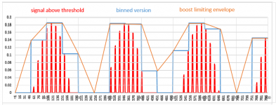
In between the attack and the release we are more or less following the contour of the signal, discretized into bins. To ensure that the boost limit is always at LEAST as much as needed I will implement a rule about how the boost across and between bins are "connected", using a linear interpolation when the boost needs to be increased or decreased. This is illustrated by the attached plot.
The attachment is a plot with three separate signals:
The main idea is to bin samples and then look for the maximum amplitude sample within each bin. If the max sample value exceeds the threshold, we them look among the N Linkwitz Transform outputs that are being calculated in parallel for the one that has just enough reduced low frequency boost to bring the sample value back below the threshold. At least this much boost limiting will be applied to all the samples in that bin.
To make the programming easier for me the bin width will be made the same as the buffer size of the LADSPA host. For example, I use a 1024 sample buffer at 48kHz and this comes to about about 2.1 milliseconds of audio data. The processing requires that a couple of bins are inspected for the max value before the samples that they contain can again be spit out, so the minimum latency should be on the order of 4 bins, or in this example 8.5 milliseconds. I previously thought that the minimum latency should be on the order of half the period corresponding to the lowest frequency and gave the example of 10Hz --> 50 milliseconds. I later realized that this is really only for the release time of the boost limiter, so that as the waveform passes through zero and then increases again you don't generate pulsing of the boost at 10Hz. While he "attack" can be on the order of one or two bin widths to make the boost decay over longer time scales I will simple slow down the rate that the limiting can fall back to zero. I figured out a straightforward way to do this.
In between the attack and the release we are more or less following the contour of the signal, discretized into bins. To ensure that the boost limit is always at LEAST as much as needed I will implement a rule about how the boost across and between bins are "connected", using a linear interpolation when the boost needs to be increased or decreased. This is illustrated by the attached plot.
The attachment is a plot with three separate signals:
- the signal that is ABOVE the threshold in RED
- the binned version of signal that is ABOVE the threshold in BLUE
- the envelope that the boost limiter will follow in ORANGE
Attachments
After a little more thinking, it looks like I will only need to buffer ONE block of audio so the latency should only be a millisecond or two. I have started to write the code to implement everything.
After a little more thinking, it looks like I will only need to buffer ONE block of audio so the latency should only be a millisecond or two. I have started to write the code to implement everything.
That's amazing. So perhaps it will be fine in a PA setting 🙂
That's amazing. So perhaps it will be fine in a PA setting 🙂
The "delay" is not so high that it would be noticeable, if by "PA" you mean in a real-time situation.
If a subwoofer uses this plugin on a separate audio channel within the DSP crossover the other channels should probably be delayed to match. This is because this amount of delay at 100Hz or 150Hz is not an insignificant amount of phase rotation. I plan to spit out some info on delay/latency when the plugin is activated, since this will vary with buffer size and sample rate. It's a simple matter to use a delay line or my mTAP delay plugin to make sure all the channels are in sync.
Beware C.L. that latency in fine *** picky discerning audiophile language is a forbidden word...
Last edited:
The "delay" is not so high that it would be noticeable, if by "PA" you mean in a real-time situation.
If a subwoofer uses this plugin on a separate audio channel within the DSP crossover the other channels should probably be delayed to match. This is because this amount of delay at 100Hz or 150Hz is not an insignificant amount of phase rotation. I plan to spit out some info on delay/latency when the plugin is activated, since this will vary with buffer size and sample rate. It's a simple matter to use a delay line or my mTAP delay plugin to make sure all the channels are in sync.
Yes, real-time situation where anything approaching 10ms can become an issue, like DJing, etc (Assuming all other channels are delayed to compensate for the delayed sub-woofer channels)
Beware C.L. that latency in fine *** picky discerning audiophile language is a forbidden word...
Ah, well... it is what it is! It's awful hard to have a lookahead feature with zero latency for a real-time application! 🙂
Actually the user has some control over this (the aforementioned "L" word). By using a smaller audio buffer "L" is made smaller. I just served up a real world example following what I mentioned before. The "L" is only one buffer long - I was using a 1024 sample buffer at 48kHz. That comes to 2.1 milliseconds. I think that I have successfully used a 512 sample buffer at this rate in the past, which would cut the "L" in half. For my LADSPA host the buffer must be a power of 2. The user could experiement, use faster hardware, etc. if "L" is to be minimized at all costs.
Ah, well... it is what it is! It's awful hard to have a lookahead feature with zero latency for a real-time application! 🙂
.
Hard but very little is impossible. Short of a time machine the lookahead would have to be predictive based on current waveform i.e. *very* high sample rates and stunningly fast response from the control circuitry would be needed, and at the end of the day the response would need to be limited over such a short time period that, even if it worked perfectly, it might be indistinguishable from a simple limiter. But it would avoid the latency 🙂
P.S. Thanks for doing all this work on LADSPA plugins. I'm just playing around listening to amplification options at the moment before deciding how to delivery the multiple channels I'll need for my 3-way actives. I do plan on taking full advantage of your work as the project progresses though

- Status
- Not open for further replies.
- Home
- Source & Line
- PC Based
- IDEA: Linkwitz-Transform LADSPA plugin with lookahead boost control