The only thing I can add to this argument is that with a conjugate network flattening the impedance it is then possible to use a textbook network design and have it actually work at the frequency that is chosen. Most simplistic network designs just assume a flat impedance matching the speakers rated impedance which we know is a very false premise. At least this makes that almost true if you could make an absolutely flat impedance curve across the FR. As far as whether Max is correct that the conjugate network on the speaker terminals will absorb the back emf from the voicecoil I'm not sure we can count on that? Any simulations that would show that to be true that the back emf would not still effect the output from the amplifier would be appreciated.
I guess we can use the term tank circuit to describe the conjugate network, does a tank circuit by itself completely counter the back emf force we are talking about from the moving voicecoil or is there a percentage leakage that is still possible through the parallel circuitry? Perhaps that is better said as a series connection to the amplifier.
I guess we can use the term tank circuit to describe the conjugate network, does a tank circuit by itself completely counter the back emf force we are talking about from the moving voicecoil or is there a percentage leakage that is still possible through the parallel circuitry? Perhaps that is better said as a series connection to the amplifier.
Last edited:
Mate we're talking about speakers here. Drowning out good posts with a huge barrage of trivial stuff might win you the forum argument, but the point is that the science wins in the end.
Then why did you bring it up? (BTW, one of the best string theorists alive is a regular poster here, just sayin')
The stuff about amplifiers makes no sense, and of course, has no data behind it. Crossover distortion, common-mode... it's like a word salad.
The only thing I can add to this argument is that
with a conjugate network flattening the impedance it is then possible to use a
textbook network design and have it actually work at the frequency that is chosen.
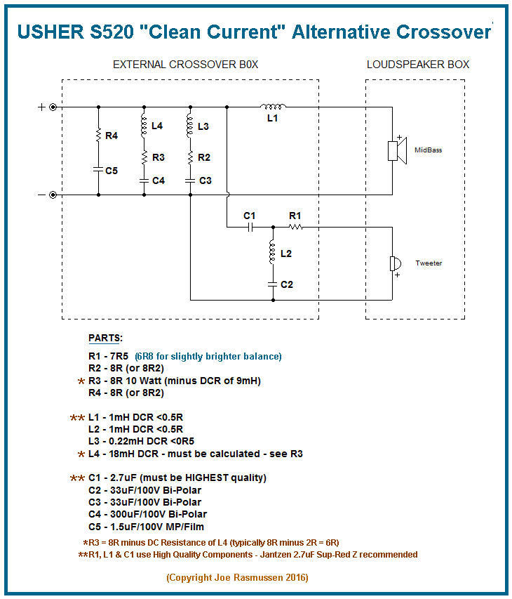
Conjugate filter (the one directly in parallel with amp out or speaker cabinet
input terminals) placed before HP and LP filter doesn't make a passive filter work
any better. It has to be after these, directly in parallel with the driver terminal to
do that. Exact changes are best seen in a sim.
Although, impedance peak of a midwoofer can be flattened with a conjugate
filter ( JR did that ), this modification only helps the amp see the impedance
less reactive.
Last edited:
Network theory/approximation states that there should be no real difference, practise says different.
Dan.
Sorry but nothing as profound as that going on here. There is no theory that says anything HAS to sound better than something else.
The schematics don't show the networks across the drivers. Look again.
Not even vaguely.
Dan, didn't you mean keeping circulating currents away from the amp feedback loop? Don't you think there may be something in that with 'some' amps?Agreed this is not optimally minimising circulating currents, and can be majorly improved as per I advocate.
Dan.
Conjugating a crossover impedance peak can produce a net impedance phase angle of zero, doesn't this imply a 'self-contained' loop?Any simulations that would show that to be true that the back emf would not still effect the output from the amplifier would be appreciated.
Yeah, sort of.Dan, didn't you mean keeping circulating currents away from the amp feedback loop? Don't you think there may be something in that with 'some' amps?
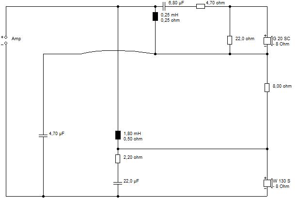
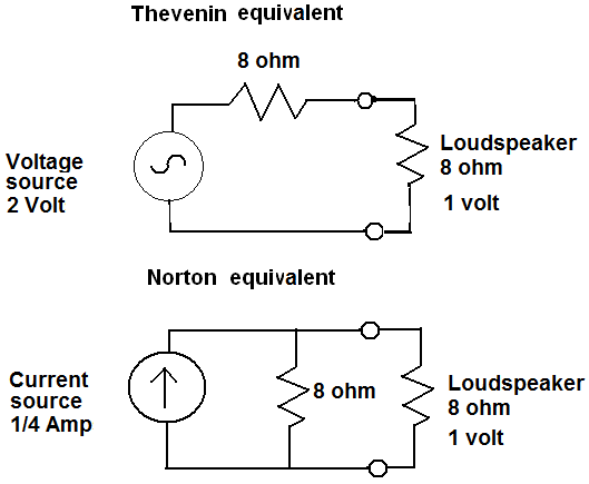
I mean to compensate the drivers right at the driver connections and end up with a loudspeaker that measures flat resistive impedance 20Hz-20kHz+.
This means no return energy for the amp to deal with, which means less FB corrections, which makes for more peaceful/accurate sound ime.
Dan.
Joe may not have wrote what he ment.
He also may not have meant what he wrote. Neither of those things would be at all surprising. Joe often claims that he did not write what he meant, or didn't mean what he wrote, or didn't write what he wrote. Let's wait and see which he denies first.
Lojzek,
I am assuming a conjugate network on the speaker terminals. between the amp and any xo or none at all if the speaker has an active filter before the amplifier.
I am assuming a conjugate network on the speaker terminals. between the amp and any xo or none at all if the speaker has an active filter before the amplifier.
Snip..
The stuff about amplifiers makes no sense, and of course, has no data behind it. Crossover distortion, common-mode... it's like a word salad.
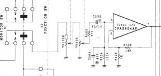
If you've built preamps and power amps and current amps, as I have, you really have three major problems. Stability in feedback, requiring compensation which reduces transient response and slewing rate or a defined stable load. Common-mode caused by earth-rail noise breaking into the signal path below with mismatched resistors in the arms in unbalanced mode:
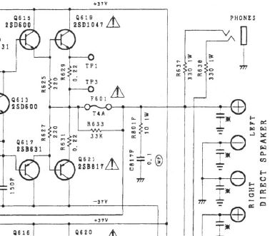
And crossover distortion which reduces current output ability at the zero volts crossing:
All these things make or break an amplifier, and IMO, get considerably easier with a flat resistive load around 8 ohms.
The discussion has moved on to conjugates, which TBH, can be placed in many places.
Joe's ideas aren't the only game in town:
You can do series crossovers:
All these things shall be washed away, like ... tears in rain...😀
Hi System7:
You keep posting the same pictures over and over again, but I don't understand what they are meant to convey.
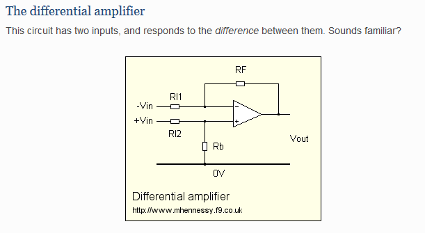
If I understand you, you are saying that currents on the ground "rail" can induce a voltage across RB and hence at the input to the amp. Where is the common-mode component? Your picture seems to show a differential-mode noise source. Can you explain how that is common-mode? Maybe you need a new picture?
You keep showing that fragment of a schematic, but I don't see the crossover distortion, nor how it varies with load. Could you please find a graphic which shows what you are talking about?
So why are you posting his schematic for the hundredth time?
You keep posting the same pictures over and over again, but I don't understand what they are meant to convey.
Common-mode caused by earth-rail noise breaking into the signal path below with mismatched resistors in the arms in unbalanced mode:
If I understand you, you are saying that currents on the ground "rail" can induce a voltage across RB and hence at the input to the amp. Where is the common-mode component? Your picture seems to show a differential-mode noise source. Can you explain how that is common-mode? Maybe you need a new picture?
And crossover distortion which reduces current output ability at the zero volts crossing:
You keep showing that fragment of a schematic, but I don't see the crossover distortion, nor how it varies with load. Could you please find a graphic which shows what you are talking about?
Joe's ideas aren't the only game in town:
So why are you posting his schematic for the hundredth time?
Has it got up to a hundred times of posting the same thing? Well, TBH, that's because we have reached a point where the same critics have said the same thing a thousandfold. 😱
Surely this thread is a battle. But it's not that hard. 😀
My point is that opamp preamplifiers often break the established rules of common-mode rejection. Below is the Rotel RA 931 preamp. Surely not wildly different from the ideal theory. But not bad, and adjustable, if you accept that the perfect is often the enemy of the good.
Attachments
System7 said:
Common-mode caused by earth-rail noise breaking into the signal path below with mismatched resistors in the arms in unbalanced mode
Nezbleu asked:
If I understand you, you are saying that currents on the ground "rail" can induce a voltage across RB and hence at the input to the amp. Where is the common-mode component? Your picture seems to show a differential-mode noise source. Can you explain how that is common-mode?
System7 answered:
My point is that opamp preamplifiers often break the established rules of common-mode rejection. Below is the Rotel RA 931 preamp. Surely not wildly different from the ideal theory. But not bad, and adjustable, if you accept that the perfect is often the enemy of the good.
Anybody ever seen a finer example of trolling and refusal to engage in meaningful discussion?
What a waste!
Jan
Last edited:
Jan,
At this point there seems to be no actual science being used here to defend or explain these positions, just redirection. Even I understand that Sys7 is not showing anything to do with common mode noise nor has anyone answered my question about a simple tank circuit and its effectiveness at removing the back emf from the moving coil. I'm not sure what any of this has to do with the original subject at this point, that seems to get lost in the haze of he said she said of non answers and the proverbial you have a closed mind.
I now see the misconception about current drive of the speaker itself as that doesn't matter whether you are using a VFA or CFA type amplifier as far as the speaker is concerned. Current is what drives the voicecoil but is doesn't seem to matter how you get there with the source amplification. Thanks for keeping it real. Just tying the speaker directly to the output of the amplifier seems to be the real critical difference between that and having a network in between an amp and the speaker terminals.
My last question becomes if you do connect directly between the amp output and the speaker terminals how about with a tweeter where you still want to protect the speaker from any dc output, how do you choose a capacitor for that, do you just use a large cap so it does not influence the active network before the amplifier or do you use a normal first order value and just use that as part of the final slope for the intended acoustical rolloff?
OK, guys, as you know I'm not a complete newbie when it comes to all this crossover and speaker and amplifier stuff. I actually know stuff. I can measure, if interested. I know the theory. I can listen to the final result.
So, er, what do you suggest I do with my speakers to make them sound better?
I mean, just throw out ideas. I'll do it. I can build most stuff. 😎
Let's see how good you are. Time will tell who's right. 🙂
So, er, what do you suggest I do with my speakers to make them sound better?
I mean, just throw out ideas. I'll do it. I can build most stuff. 😎
Let's see how good you are. Time will tell who's right. 🙂
Attachments


Kindhorman, I am not a speaker guy but for the tweeter cap I would think it sensible to incorporate it into the xover. Two birds and one stone and less cost and such. But design may dictate otherwise, possibly.
BTW I do think there is merit in some form of current drive, and if you can bring yourself to read past the frustration and arrogance in Esa's book, there are gems to be found. Unfortunately our OP and his groupie have shown a total lack of understanding of it.
Jan
BTW I do think there is merit in some form of current drive, and if you can bring yourself to read past the frustration and arrogance in Esa's book, there are gems to be found. Unfortunately our OP and his groupie have shown a total lack of understanding of it.
Jan
jan.didden as a self-acknowledged less than knowledgeable person on speakers, why ever are you seeking to advise people about them? 😕
You clearly also know even less about current drive than most.
I have built this stuff. I know how it works and Joe Rasmussen with his flat resistance ideas is nearer right than you are. But, hey, fools must pretend to be wise, eh?
BTW, thank you for taking us off-topic. Nothing like distracting from the real issues. Now can we get back to my inconvenient Real World speaker. Any ideas?

Not really. 🙄
You clearly also know even less about current drive than most.
I have built this stuff. I know how it works and Joe Rasmussen with his flat resistance ideas is nearer right than you are. But, hey, fools must pretend to be wise, eh?
BTW, thank you for taking us off-topic. Nothing like distracting from the real issues. Now can we get back to my inconvenient Real World speaker. Any ideas?
Not really. 🙄
There should be limit set on the amount of times you are allowed to post the same image.
Steve, we are just asking you to explain what you mean. If a flat impedance is a good thing then why?
Steve, we are just asking you to explain what you mean. If a flat impedance is a good thing then why?
Last edited:
jan.didden as a self-acknowledged less than knowledgeable person on speakers, why ever are you seeking to advise people about them? 😕
You clearly also know even less about current drive than most.
Context is all. Kindhornman IS a speaker designer. Jan is not. However I am willing to bet he understands the issues with speaker design more than you do. When you hang around with acknowledged experts in the field a teensy bit of humility is very useful as you will always know someone who understands things to greater depth than you do.
Netherlands AES Section Note Jan does hang around with a lot of real experts, not just internet keyboard warriors.
He can't even read accurately. I said I am not a speaker guy, NOT 'I am not a speaker designer'. I designed a speaker a few years ago just for fun to see if I liked it, and so far 30 pairs have been build by others because they really liked the sound.
But, no I am not a speaker guy, I like to dabble more in electronics.
Jan
But, no I am not a speaker guy, I like to dabble more in electronics.
Jan
- Status
- Not open for further replies.
- Home
- Loudspeakers
- Multi-Way
- Joe Rasmussen Usher S520 "Current Compatible" Crossover