This is how I "grounded" the pot. Before, I had similar problems. What is your source? My worst was poorly grounded TT preamp. I had to make an earthing extension cord and connect it to the preamp.Here is a recording of the noise. The louder buzzing that goes on and off is what happens when I touch the pot. I'm guessing I can solve that by grounding the front of the pot. The quieter interference noise I am not sure about outside of better decoupling. Hopefully this link works for you guys.
https://drive.google.com/file/d/0B6f6pS_SoEYMUFh4elV6MWY2TDg/view?usp=docslist_api

Yes I know all my source wires are a mess... And so is colour coding. Will strand them or sth when I make an enclosire for my new 3118 boards🙂
Last edited:
I checked your sound sample. The smaller noise sound like some radio interference or similar, maybe an interference of pwm-clock with something else.
The loud noise is obviously mains hum. Interesting to hear american 60Hz mains hum definitely sounds different to european 50Hz.
The loud noise is obviously mains hum. Interesting to hear american 60Hz mains hum definitely sounds different to european 50Hz.
Here is a recording of the noise. The louder buzzing that goes on and off is what happens when I touch the pot. I'm guessing I can solve that by grounding the front of the pot. The quieter interference noise I am not sure about outside of better decoupling. Hopefully this link works for you guys.
https://drive.google.com/file/d/0B6f6pS_SoEYMUFh4elV6MWY2TDg/view?usp=docslist_api
Both tpa's are set for master 26dB ?? And you have left the synch connection between chips as it was ?? In that case remove the ceramic cap between the tpachips, maybe both the cap and resistor, the link between both synch
Last edited:
Yes I know all my source wires are a mess... And so is colour coding. Will strand them or sth when I make an enclosire for my new 3118 boards🙂
I see nothing wrong with this setup 😀
My source is generally my phone (Samsung Galaxy S5), this recording was taken with nothing on the input, but it sounds exactly the same with my phone is plugged in with no signal on the line.
I checked your sound sample. The smaller noise sound like some radio interference or similar, maybe an interference of pwm-clock with something else.
The loud noise is obviously mains hum. Interesting to hear american 60Hz mains hum definitely sounds different to european 50Hz.
The loud hum is no doubt the 60Hz mains noise, and I agree, always strange when I hear the 50Hz European hum on youtube videos, so familiar, yet so different.
Radio interference was my first guess based on the sound. Only time I have heard similar was when I was playing with a "foxhole radio" I had accidentally built, and in some old Sci-Fi movie about Mars and the alien signal sounded similar to that. I thought these chips had radio interference suppression built in though? Back to the datasheet.
Both tpa's are set for master 26dB ?? And you have left the synch connection between chips as it was ?? In that case remove the ceramic cap between the tpachips, maybe both the cap and resistor, the link between both synch
This is correct. Out of the box it came setup as dual master with 36dB gain, and the synch connection was as shown in that image. I don't think my Fluke 87V will read down in the pF range, but I can always get a known cap value and set them up as master/slave if that would work better. For now I will remove the synch resistor and cap to let them run fully independent.
OT: The "foxhole radio" that I have heard this sort of interference on before is actually a funny story. It was actually an inline smartphone mic, that didn't work for its intended purpose at all. So I plugged it into my computer and listened to the device while I took it apart, and I noticed if I touched my screwdriver to the metal face of the buttons I would start to pick up AM radio stations, different tuning depending where and which button I was touching, Thought it was pretty cool, though totally useless at the time, because what I needed was a microphone 😀
Yes it does, whether it is connected to the SMPS inside the brick or not, I have no clue. The AC input socket on the power brick has the ground pin, as does the cable, but in my experience with Chinese goods, that doesn't mean it is actually connected to anything internally.
Well there's something to investigate🙂 In my experience, humming always had something to do with grounding. The only hum I cant get rid of is the noise my plasma tv emitts to my amp when bright picture is on.Yes it does, whether it is connected to the SMPS inside the brick or not, I have no clue. The AC input socket on the power brick has the ground pin, as does the cable, but in my experience with Chinese goods, that doesn't mean it is actually connected to anything internally.
With many hifi components the third isn't connected to anything either, Dell and HP laptop powersupplies I have do not connect earth either (irrelevant but indeed made in china as almost everything these days)
Yes it does, whether it is connected to the SMPS inside the brick or not, I have no clue. The AC input socket on the power brick has the ground pin, as does the cable, but in my experience with Chinese goods, that doesn't mean it is actually connected to anything internally.
Well..
😀🙄
Attachments
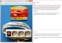
Inspections in the EU throw **** like this out very quickly. 🙂 The third wire is for safety anyway. But it definetely helps with noises sometimes. I had problems with rega rp1 paired to rega preamp. None of these devices has proper grounding, cheap tpa boards also arent earthed in any way, so it hummed like crazy. Had to use a schuko plug and only connect the third (earth) contact and connect it the preamp body. No more noise🙂
Poslano z mojega LG-D855 z uporabo Tapatalk
Poslano z mojega LG-D855 z uporabo Tapatalk
Thankfully mine has all 3 conductors. I have so many of the C13 cables that whenever I get a new one I check it, I would really not want to use a faulty one with something that has a metal case. No clue about inside the brick though. Will investigate.
Hi fellow members,
Most of the times I gather from diyaudio.com forums the information I need. This time I need a little bit info from the experts in this thread on the TPA3116.
I like to implement and combine 3-speakers (center, R and L) in two current projects. One is for a flat screen TV with separate front and center peakers, the other is to setup internet radio in a vintage radio from the fifities with 3 build in speakers.
I have read in other threads on diyaudio.com about 'Making 3 front channels out of stereo signal' and 'Trinaural decoding equations for 3 speaker stereo matrix ?'. In order to get a center (mono) and R + L channels combined you need an amplifier that can be bridged to accomodate such circuits. This led me to the TPA31XX type of D amps which in principle can be bridged. A number of car amps can also be bridged but they are much more expensive, rather large and mainly class AB.
I like the class D amp boards and have build several amps based on TA2024, TK2050 T2 and lately an Hypex UcD180.
After reading the first 200 posts I could not really distill a good answer.
Is there anyone among you experts who has either experience in such a set up with TPA31xx or can make further suggestions?
Thanking you in advance,
Kornelis
Just check resistance between PE-terminal of AC-plug and secondary ground output. If you measure <1 Ohm protective grounding should be ok.Thankfully mine has all 3 conductors. I have so many of the C13 cables that whenever I get a new one I check it, I would really not want to use a faulty one with something that has a metal case. No clue about inside the brick though. Will investigate.
It is a well known fact that any switchmode power supplies inject considerable, audible noise current into the secondary circuit due to their in-built Y-caps. For that reason you definitely need secondary circuits connected to PE.
Last edited:
I've been thinking through a 3x driver single stereo loudspeaker for a while, and came to the conclusion that you couldn't use the TPA3116 with three drivers wired in a matrix, as the - output for each channel isn't a common ground. I plan on using two input transformers with split secondaries before the amp to generate mid and side channels from a stereo source, run these into the TPA3116 and drive 2x speakers in series/parallel (depending on impedance) on the mid channel output, and 2x speakers out of phase in series/parallel as the side output pair.
I've been thinking through a 3x driver single stereo loudspeaker for a while, and came to the conclusion that you couldn't use the TPA3116 with three drivers wired in a matrix, as the - output for each channel isn't a common ground. I plan on using two input transformers.....
What about the 2.1 board version of the TPA3116/3123?
A second 31xx chip is bridged to deliver a twofold increased output for the subwoofer. One could possibly use the (mono) subwoofer channel as a center channel when one would be able to somehow remove the low pass filter. This solution would be sufficient I think for my 3-channel radio project.
What remains is the more elaborate 3-channel stereo for my living room setup. Ideally the 3 channels are connected with each other in a so called 0.5 matrix which requires a common ground.
Something went terribly wrong with post #9116. I'm sorry about that. Moderator please remove this post.
 done.
done.Hi guys...I am having a problem with new board. At full volume and havy bass it shuts (quiets) down for a moment. This is a latest model of 2.1. I haven't had any problems with my previous model of same board.
Here is the picture of new board
https://www.dropbox.com/s/h1pgobz73le3osj/20160327_084629.jpg?dl=0
and the old one...
https://www.dropbox.com/s/gzrqn45n7fi685f/UT8g89HXxJXXXagOFbXo.jpg?dl=0
I see the main difference is that the older had 3 main capacitors of 2200uf and the new one has 2x3300mf + a smaller 220uf on the middle.
Anyone has idea what is the problem and how to fix it?
Thanks
update...I just remembered I have a damaged red yj board with black 10000uf capacitors....have connect them from the back to first cappacitor and looks like the problem is fixed. So probalby the capacitors are too week?
Last edited:
@sharpi31
This is an interesting idea. I am not shure that I can follow you one hundred percent on this, especially regarding the transformer part. Could you please illustrate your proposed circuit in a diagram for a non-electronic engineer like me?
I plan on using two input transformers with split secondaries before the amp to generate mid and side channels from a stereo source, run these into the TPA3116 and drive 2x speakers in series/parallel (depending on impedance) on the mid channel output, and 2x speakers out of phase in series/parallel as the side output pair.
This is an interesting idea. I am not shure that I can follow you one hundred percent on this, especially regarding the transformer part. Could you please illustrate your proposed circuit in a diagram for a non-electronic engineer like me?
- Home
- Amplifiers
- Class D
- TPA3116D2 Amp