Hi Karl, just sent you a mail but i thought i would post here for ref and in case you catch this first.
Iv'e finally got round to building my amp, im a bit confused on the cable that runs to the display, the schematic on your site shows black red and green, ok im guessing white is meant to be green so ive hooked that end up on the green pcb as per block diagram. now theres no detail on the schematic for the display side of the cable, ive got: IN V+ 0V so at the green pcb, i have white on G and black on D. Does Black go to IN or is it 0V at the display end? Apologies if ive missed something obvious.
Alan
Hi Karl, just sent you a mail but i thought i would post here for ref and in case you catch this first.
Iv'e finally got round to building my amp, im a bit confused on the cable that runs to the display, the schematic on your site shows black red and green, ok im guessing white is meant to be green so ive hooked that end up on the green pcb as per block diagram. now theres no detail on the schematic for the display side of the cable, ive got: IN V+ 0V so at the green pcb, i have white on G and black on D. Does Black go to IN or is it 0V at the display end? Apologies if ive missed something obvious.
Alan
Alan, glad to hear you've finally got the time to get to it. Sorry about the confusion -- I should have labelled the Display end of those lines. I'd make them match up on the PCB, but I don't manufacture the board on the OLED end.
Ground = "G" on controller board = "0V" on display board
+5vdc = "+" on controller board = "V+" on display board
Data = "D" on controller board = "IN" on display board.
On this cable, I prefer to look for the black conductor and plug that side into the "G" and "0V." If you do that, you'll always have it right.
Last edited:
Oh and i was wondering if the ir pickup would still work if its on a 20cm cable?
Should be no problem at all. If you want to avoid soldering and keep the connections easy to move around, you could go to an RC hobby shop and buy a 3-conductor cable like the display cable, and simply plug the sensor into one end, and use pins in the screw terminals so you could then simply plug the other end of the cable in also. (Observing polarity, of course.)
Fantastic, thanks for that, im going to see if remote commands will work through the holes in the top of my case to save me making a hole in the front panel, i will report when its all done, was up till 3am last night and still loads to do so maybe next weekend.
Alan
Alan
A customer recently ran the LDR control board through a technical evaluation using test equipment that found that channel-to-channel tracking was typically within about 0.1dB across the control range but could be as high as 0.5dB for small sections of the range.
Upon investigating, I found that this is caused by an occasional calibration point that is slightly off ideal, an error that occurs rarely -- typically no more than one point on one channel per calibration or not at all -- but still could occur.
I have made changes to the calibration routine that greatly reduces or eliminates the possibility of this happening, and the time penalty for this more reliable calibration is one minute -- from twelve minutes to thirteen minutes for the typical calibration run.
This chip also corrects a small problem when using a potentiometer-based balance control (does not affect the rotary encoder). When moved slowly (real-world use) it works perfectly. However, if "slammed" from one extreme to the other, it works to the left but not to the right. This problem is resolved and the balance control now works perfectly in all circumstances.
Customers who have previously purchased this LDR board should contact BTFSystems to receive a free replacement control chip.
Last edited:
A customer recently ran the LDR control board through a technical evaluation using test equipment that found that channel-to-channel tracking was typically within about 0.1dB across the control range but could be as high as 0.5dB for small sections of the range.
Upon investigating, I found that this is caused by an occasional calibration point that is slightly off ideal, an error that occurs rarely -- typically no more than one point on one channel per calibration or not at all -- but still could occur.
I have made changes to the calibration routine that greatly reduces or eliminates the possibility of this happening, and the time penalty for this more reliable calibration is one minute -- from twelve minutes to thirteen minutes for the typical calibration run.
This chip also corrects a small problem when using a potentiometer-based balance control (does not affect the rotary encoder). When moved slowly (real-world use) it works perfectly. However, if "slammed" from one extreme to the other, it works to the left but not to the right. This problem is resolved and the balance control now works perfectly in all circumstances.
Customers who have previously purchased this LDR board should contact BTFSystems to receive a free replacement control chip.
So glad you made it with sockets, and thats really good service, makes me feel even happier with my decision to run with your setup. 😀
When can we buy one! Lol.
Sorry, I just noticed this question. I have been in the process of selling one house and buying another, and am now renovating and will then be moving 25 years of accumulated 'stuff' to the new house, so technical development is on hold until I get my new digs in operation. It'll be May before I can address this again; however, a lot of the work is already done so once restarted, should happen fairly quickly.
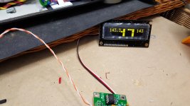
Ok ive hooked it up before i install and I have a couple of questions, as you can see from the pic the milliamp setting on the left has a decimal, the .3 is obscuring part of the volume display, is this normal? Also I cant seem to get rid of the milliamp display or switch to Balance, is this because I have no input on the board? ive tried changing the length of time to pause the push of the encoder but I can only get it to mute. (quick push) Ive also just realised that the milliamp reading is way to high!
Definitely something not right because i thought I would try calibration, the plug has no effect.... 🙁
Definitely something not right because i thought I would try calibration, the plug has no effect.... 🙁
Attachments
Last edited:
Ok ive hooked it up before i install and I have a couple of questions, as you can see from the pic the milliamp setting on the left has a decimal, the .3 is obscuring part of the volume display, is this normal? Also I cant seem to get rid of the milliamp display or switch to Balance, is this because I have no input on the board? ive tried changing the length of time to pause the push of the encoder but I can only get it to mute. (quick push) Ive also just realised that the milliamp reading is way to high!
Definitely something not right because i thought I would try calibration, the plug has no effect.... 🙁
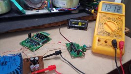
I wish I had better news for you. In your picture it appears you've connected the 12V power supply to the 5VDC output terminals.
The +12V input terminals which deliver power to the input side of the on-board regulator are at the far end of the terminal strip and are marked 9~16VDC In. Look at the wiring schematic under the technical tab at BTFSystems LLC - BTFSystems LDR passive preamp, and you will see the error.
The 143.3 is what you get when the rotary encoder board is working properly but the LDR controller board is not providing it with any useful information to display.
You need to move the 12 volt supply wires off of the +/- 5V output screw terminals and connect them to the +9~16V input screw terminals on the LDR control board.
That will not solve your problem because you have been delivering 12VDC to a 5.5VDC MAX chip so it probably did not survive. Even if it appears to work, it is no longer reliable, so I will send you a new chip on Monday.
Karl
Last edited:
Thats what happens when your in a hurry, i checked the schematic on your site then hooked it up to the wrong part, will test it again. Thanks for the prompt reply Karl.
Its looking promising, i turned it on and it started calibrating even though i had removed the plug so i turned it off and put the plug in, its doing its thing now so i have everything crossed with a very red face.
I wish I had better news for you. In your picture it appears you've connected the 12V power supply to the 5VDC output terminals.
The +12V input terminals which deliver power to the input side of the on-board regulator are at the far end of the terminal strip and are marked 9~16VDC In. Look at the wiring schematic under the technical tab at BTFSystems LLC - BTFSystems LDR passive preamp, and you will see the error.
The 143.3 is what you get when the rotary encoder board is working properly but the LDR controller board is not providing it with any useful information to display.
You need to move the 12 volt supply wires off of the +/- 5V output screw terminals and connect them to the +9~16V input screw terminals on the LDR control board.
That will not solve your problem because you have been delivering 12VDC to a 5.5VDC MAX chip so it probably did not survive. Even if it appears to work, it is no longer reliable, so I will send you a new chip on Monday.
Karl
I didnt finish reading all your post, let me know how much I owe you Karl and thanks for the great service.
Yeah ive killed it, most expensive set of pcb's ive ever purchased and i hooked it up wrong, cabbage...... Oh well at least i will now get the chance to listen to my amp with a standard pot before i use an LDR, silver lining but apologies to Karl.
I didnt finish reading all your post, let me know how much I owe you Karl and thanks for the great service.
No charge for the new chip because it also corrects a minor coding error in the balance control.
Yeah ive killed it, most expensive set of pcb's ive ever purchased and i hooked it up wrong, cabbage...... Oh well at least i will now get the chance to listen to my amp with a standard pot before i use an LDR, silver lining but apologies to Karl.
Well, you haven't smoked the whole pcb set -- just one chip, so no big deal aside from the delay.
No charge for the new chip because it also corrects a minor coding error in the balance control.
Well, you haven't smoked the whole pcb set -- just one chip, so no big deal aside from the delay.
Many thanks Karl, a little delay I can handle if I havnt done any more damage, very happy here!
Thinking it through, it's possible the LDRs and the status LED are damaged because current-limiting for those devices is calculated based on a 5 VDC source. I can't be sure because current through those devices depend entirely on the output state of the chip when it failed. so if it failed with those circuits turned off, then no harm done. If the circuits were turned on, then probably there's damage.
If you can test the LDRs and status LED out of circuit, that would be useful. You should deliver about 10 milliamps at 2 volts. The status LED should light up, and the LDR resistance should drop down to 35~80 ohms.
Also, some of the tantalum capacitors have voltage ratings below 12 volts but probably are OK. The mosfets certainly are OK. The voltage regulator should be OK; if it's working, then it's OK.
IF the rotary encoder board is working OK then the data exchange wires did not deliver high voltage to the encoder board.
Ok, Im affraid i need a little help!
So i need to pull the LDR's out of the sockets?
Which pins do i connect it to and what size resistor do i need to deliver or limit current to 10milliamps?
What is the Status LED?
Do I use a DMM to measure there resistance and how is this achieved?
Sorry for all the questions, I have no experience with LDR's but I would very much like to test them. The biggest problem is probably finding something that will supply 2v, will a 1.5v battery do the job? 2 to make 3v?
- Home
- Vendor's Bazaar
- BTFSystems precisionLDR modules for digitally-controlled LDR Passive Preamp