Williamson open loop stability question
All the complaints I've seen of instability in Williamson amps are due to the multiple stages within the global negative feedback loop. But what about the circuit's open loop behavior? If one were making a push-pull 300B amp, or some other PP amp that didn't use a gNFB loop, would a Williamson driver be any better than the more commonly seen circuits like variations on the Mullard 5-20, or the various 'dual-differential' circuits?
I like the idea of using a cathodyne phase splitter for its good balance. The first stage voltage amp would be single-ended, which is not a bad thing if done right. One could even DC-couple the push-pull driver (after the cathodyne) to the output finals, which would help with blocking behavior. Only one AC-coupling necessary (between cathodyne and PP driver stages).
If I used all low-mu tubes in the gain stages, and something like a triode-wired, high mu/high gm RF pentode for the cathodyne, it should make for a nice driver for PP 300B's or something like that. Right?
I figure if it's such a good idea, somebody must have already done it. But I don't see anything like that on the innerwebs. I must be missing something...
--
Rongon
I have made several amps using Low Mu 6BL7's/6BX7's direct coupled cathode followers, to output stage. What improvement would you get by using " triode-wired, high mu/high gm RF pentode"? Are there any triode-wired, high mu/high gm RF pentode that can handle high voltages with good plate dissipation? Some DIY's use Mosfets.
thanks
Phil
I was thinking one would want high mu to reduce distortion (more feedback in the cathodyne). It would also be nice to have low rp, which means high(ish) gm.
Why is it necessary for the cathodyne stage to handle higher voltages than about 150V plate-cathode (or cathode-ground)?
The 6688 in triode would be good enough, I think. It would run on about 10 to 15mA plate current, with a mu of about 35 or so. I suppose D3a, 7788 or 6J52P would be even better, but then there's microphonics to worry about.
I'm thinking of using triode-wired GU50's as the finals, with something like a 6J5 as the common-cathode input stage. Something like triode-wired 6V6's as the push-pull driver stage.
I'd be using the GU50-triodes with no more than 350V plate-cathode, in PP class A or AB1. I figure the grid bias would be about -50V.
Coming very late onto this thread and having read the lot in one go, I trust that Eddiegnz1 will allow just a few general comments, not just pertaining to the Willaimson but also some other matters touched on here?
It is with some sadness that one feels like paraphrasing Douglas Self, where he said that in most branches of engineering progress is defined by precise standards and measurements, but in audio some people seem to be confused about which way forward is. No, I am not going to try challenge the saying "Entrenched beliefs cannot be changed by facts". Worthier individuals than myself have failed .....
About Williamson first, I would consider it fair to rather refer to the topology than focus on small failings. (It is a little like that other maxim that in sports those who came out top are then judged by their worst or last game.) Thus overlooking the rather obvious little thing of choosing a less than perfect l.f. roll-off, perhaps just for a minute one can notice that the open loop response is down about 1,5dB at 20kHz and 1,5dB at 20Hz; a phase deviation of 45 deg at 20 Hz and about 10 deg at 20kHz; to close off with some 0,5% distortion at 12W output - all before any nfb.
Which of the much lauded amplifiers not using evil NFB can equal that? The Williamson can then still beat most of the other gems in the zero-nfb field. And about 20 dB of nfb being high - facts have been given. Some commentators have perhaps not been in the field very long. No further comment about that; as said "entrenched beliefs .... "
[Despite that I found myself having used the "Leak/5-20" type topology rather more often. While that being off-topic, I will just say that I prefer a properly fasioned pentode input directly coupled to a medium/low gain Schmitt (long-tailed pair) to the Beirith conversion. Properly designed pentode input stages have about 20% of the distortion of similar triodes, apart from the advantage of the input impedance having negligible effect on total response in the absence of Miller effect. The driver is best a rather more robust medium gain tube, not the high-impedance 12AX7. But I respect Mr Bayrith trying to effect the least changes. Etc.]
There are only so many topologies for tube amplifiers. Do the basics right instead of sniffing snake oil, and one will be hard-put to improve on the Williamson topology.
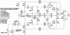
Concertina with equal Z's, voltage gains, and de-blocking.
Compared to Williamson: Similar open loop gain with one
less stage, and one less cap shift in the loop.
Er, No... This drawing is two less stage and two less caps.
You could stick another half 12ax7 up front, then it'd be
comparable open loop (less one cap) to Williamson.
I'm sure it started that way (with 2 stages of triode voltage
gain). Must have ditched one of them as unnecessary while
I was tweaking the de-blocker? Can't remember now...
I look back now, exactly what the hell was I thinking?
My old PWilSoup drawing used both halves 12ax7 for gain.
But lacked the de-blocker, yeah thats what was going on...
So, this de-blocker tries to keep the average of both drives
at -29VDC thereabouts. Will pull up only on whichever side
is in cut-off, so's hopefully not to be heard. Does nothing
and tries to be harmless except when there is grid current.
Attachments
Last edited:
best possible power supply?
@Defiant
Apologies for repeating the question:
Why is the power supply in the Byrith paper so abysmal and what would you suggest to improve this? I noted that Byrith offers 2 alternatives one with caps only and one C-L-C filter input.
While I can see some improvements, you seem to have a strong opinion about this. Care to share?
... Fortunately a good power supply solves these problems. Unfortunately, the author of that article recommends the worst possible power supply configuration.
@Defiant
Apologies for repeating the question:
Why is the power supply in the Byrith paper so abysmal and what would you suggest to improve this? I noted that Byrith offers 2 alternatives one with caps only and one C-L-C filter input.
While I can see some improvements, you seem to have a strong opinion about this. Care to share?
What about this?...
Say you make a two-stage 'output module' consisting of the OPT, output tubes, and differential driver stage. Think of it as the last two stages of a Williamson, with its own power supply. You could use plate-grid feedback around the output tubes, or feedback from the output tubes' plates to the driver tubes' cathodes.
Second, make a two stage 'preamp-phase splitter' in a separate box with input switching and volume control, basically like SY's Impasse preamp. Think of it as the first two stages of a Williamson with its own enclosure and power supply, with built in input switching and volume control.
There would be no global NFB loop, so stability shouldn't be such an issue.
There could be feedback to linearize the output stage, which is where most of the distortion occurs.
The 'preamp-phase splitter' could be designed to swing plenty of volts.
The differential driver could be made of something really brawny, like a pair of triode-wired EL84's or 6V6's. Or maybe a 6N6P.
It would be huge, but it would be a sort of integrated amp in concept.
Good idea? Stupid idea?
--
rongon, perhaps the easiest way to really assess an idea is to 'design it up' - then all the nitty gritty practical issues are faced, and hopefully solved. That process can be very enlightening, as it requires a good understanding of all interactions.
Others can then inspect your idea, knowing that you have done the hard yards of putting it on paper and even confirming some performance aspects.
It took me quite a while just to go through all the original design issues and the early proposed changes of the Williamson amp - not a simple task in itself:
http://dalmura.com.au/projects/Williamson%20design%20info.pdf
Ciao, Tim
The Williamson is a good design. I particularly like the cathodyne use. I've simmed the cathodyne using 6SN7 in LTspice and it has an MU of slightly better than 16 at the output of the cathodyne. That's pretty darn good for a two tube voltage gain/phase splitter using the lowest distortion tube around - the 6sn7.
It seems to me a good modern interpretation is to find an output tube than can get by with that gain of 16 and lose the driver stage. Simple is better. Who needs 20db of feedback. 6db should be sufficient in a good design. EL84s will work here. Maybe 6V6. If you are not getting the power out that the original Williamson had then use two parallel el84s or 6V6s. I've simmed that topology of 2 parallel el84s driven by tubelabs' power drive and it simms at 60 watts in pentode. Better than 45 watts in triode. The mosfet followers makes non-issues of miller capacitance of parallel tubes, along with all the vast other benefits of using that topology.
It seems to me a good modern interpretation is to find an output tube than can get by with that gain of 16 and lose the driver stage. Simple is better. Who needs 20db of feedback. 6db should be sufficient in a good design. EL84s will work here. Maybe 6V6. If you are not getting the power out that the original Williamson had then use two parallel el84s or 6V6s. I've simmed that topology of 2 parallel el84s driven by tubelabs' power drive and it simms at 60 watts in pentode. Better than 45 watts in triode. The mosfet followers makes non-issues of miller capacitance of parallel tubes, along with all the vast other benefits of using that topology.
I should add there is basic change in the requirements for modern day amplifiers compared to many of the vintage examples. For some reason it may not have sunk in when trying to adapt those examples. One generally does not have to amplify a very low voltage source signal anymore. And if you do - well that's what preamplifiers are for. It completely changes gain structure required of amps and the choice of VT. I say stick with the 6sn7 for it's fine characteristics. But if you need more then just use one gain stage of 6sl7 (as an example). Remember, using the cathodyne one will have double the voltage gain of the same two tubes using an LTP.
EDIT:Actually one might have problems using a 6sl6 in a cathodyne. Things like heater/cathode breakdown because the cathodyne section has the cathode at high voltage.
EDIT:Actually one might have problems using a 6sl6 in a cathodyne. Things like heater/cathode breakdown because the cathodyne section has the cathode at high voltage.
Last edited:
The Williamson was designed for about 1.4Vrms max output sources - just right for modern soundcard DAC outputs running off 5V rails 😉I should add there is basic change in the requirements for modern day amplifiers compared to many of the vintage examples.
Yeah, I really like the 6sn7 not only for it's low distortion, but also because it sits right in the sweet spot where it can accept hot signals in addition to the vinyl that existed in the day. I just meant one should never assume you need the same level of total voltage gain in a amp today that they required back then. If one needs to make a modification to update the Williamson that always seems to be the part that gets ignored. Human beings are creatures of habit.
Well, the reason I arrived at this was because I've already basically built a prototype.
I originally wanted to have a 2-stage DC-coupled Push-Pull 2A3 amp, which I built using a 5687 driving the PP 2A3's. There's an 'autoformer' as center-tapped plate load for the 5687 driver. I originally had it rigged up as an LTP with a -60V negative tail supply and a 2k2 ohm tail resistor. I then changed that to a -20V supply and used a simple LM317 CCS. The resulting amp required about 3.5V RMS signal input to get to full power (only 6W per channel), so I had to use a preamp with gain. I was using a standard 5687 common cathode stage with input selector and volume pot.
Then I started hanging out here and tried a bunch of stuff, including a 15k:15k input transformer before the push-pull driver stage to do the phase splitting. That meant I could do away with the negative DC supply in the tail. Finally, I built a simplified version of SY's Impasse preamp, which is a 6SN7 common cathode stage into a 6DJ8 split-load phase splitter, got rid of the input transformer, and converted the input of the power amp module to balanced.
So now I basically have a Williamson-style topology, but with a center-tapped choke (autoformer) in the push-pull driver plates, with that stage DC coupled to the push-pull output tubes. There is no global NFB around any of the stages. I can get away with that because of the DHT output stage. The penalty is very low output power for the size, cost and heat dissipation. I like the sound of it, but it looks like the experimental project it is.
I was thinking of making a cleaner version, using something like 6AV5GA output pentodes with plate-grid feedback fed by a (differential) push-pull driver stage, preceded by the usual first two stages of a Williamson (i.e., an Impasse preamp). The only negative feedback added would be the plate-grid feedback around the output 6AV5GA's. I think that means the push-pull driver stage will need to be changed to pentodes (for the high rp). Or maybe I can take feedback from the output tube plates to the cathodes of the driver triodes?
I'll need to sim the last two stages to see if I can get something that looks workable.
--
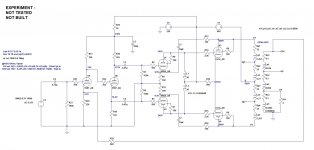
I whipped this together in LTspice.
Input common cathode stage and split-load phase splitter are a 5687 with 230V B+.
Push-pull driver stage is two triode wired EL84 with center-tapped plate load choke. 250V B+.
Output stage is two triode wired EL34 with Dyna A470 OPT, 400V B+.
-6dB NFB taken from EL34 plates to driver stage cathodes.
-6dB global NFB taken from OPT secondary to input stage cathode.
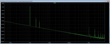
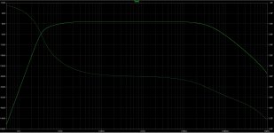
At 1 watt output into 4 ohms, spice says it'll get 0.065% THD, with 0.24% at 10 watts out. I know that's only from simulation, but it compares favorably to other modeled circuits.
What do you think?
Input common cathode stage and split-load phase splitter are a 5687 with 230V B+.
Push-pull driver stage is two triode wired EL84 with center-tapped plate load choke. 250V B+.
Output stage is two triode wired EL34 with Dyna A470 OPT, 400V B+.
-6dB NFB taken from EL34 plates to driver stage cathodes.
-6dB global NFB taken from OPT secondary to input stage cathode.
At 1 watt output into 4 ohms, spice says it'll get 0.065% THD, with 0.24% at 10 watts out. I know that's only from simulation, but it compares favorably to other modeled circuits.
What do you think?
Attachments
What about this?...
Say you make a two-stage 'output module' consisting of the OPT, output tubes, and differential driver stage. Think of it as the last two stages of a Williamson, with its own power supply. You could use plate-grid feedback around the output tubes, or feedback from the output tubes' plates to the driver tubes' cathodes.
There could be feedback to linearize the output stage, which is where most of the distortion occurs.
--
I've tried the output plate to grid method and never found it rewarding, as it decreases the input grid impedance/ raising distortion in the hard worked driver or phasesplitter drive, and considering HV components would be required. If you like transformers as I do; a habit or/ one small way of reducing thd in the output stage is to select the anode-anode load imp slightly higher than the design theoretical, as a small sacrifice to output power. Many tube data sheets do actually show the correlation and is a method I often use.
r:-
I use 6P15P pentode LTP in a driver with 1K resistors in cathodes, works great. 240K from anodes of GU-50 tubes to anodes of 6P15P. It is a nested feedback only, shorter one than the global loop.
If you're going to use local loops in the output stage, perhaps you might consider going to pentode? The higher open loop gain can be put to good use linearizing things.
Rich's comment about the effect of the feedback on input impedance is very important to consider.
Rich's comment about the effect of the feedback on input impedance is very important to consider.
Thanks for the insights everybody.
@richwalters -- Yup, I agree with you on both points. The driver stage becomes the heavily worked one. Spice shows that a relatively brawny EL84 or 6P15P there lowers distortion compared to something like a 5687 or 6SN7. It's probably the high-ish gm and reasonably high gain helping to drive the lowered impedance of the output tubes with local NFB.
Re: higher Z OPT's, yes, I like that too. I had a pair of UTC LS-63's at one point (10k:VC) and found that (if using triodes) distortion was reduced, but so was output power. I should have kept them, but I sold them. Oh well. Maybe an Edcor 8k:VC OPT is in my future.
@ Wavebourn -- I've been playing around with an Ayumi N model of 6P15P and it does model really well.
I have two feedback loops in the sim. EL34 plate to EL84 cathode (local around the output stage) and global from OPT secondary to cathode of input stage 5687. I played with R values to get -6dB from each of those two loops, so -12dB NFB total (I think). I didn't want to pile on a lot of feedback in any one place. Went for small doses of NFB spread between two locations. Does that matter? Or is -12dB of NFB the same no matter where it comes from? (In which case, is instability equally likely with -12dB NFB whether it comes from two nested loops or one global loop?)
@ SY -- I have a reasonably good input-and-phase-splitter-in-a-box setup. It's a sorta/kinda Impasse in an old Dyna PAS chassis. I can use that as a 'control preamp,' and make an experimental two-stage 'speaker amp' in a second box.
I don't have any EL34's handy, but I have plenty of 6L6GC's from my guitar amp parts stash. Maybe use those in pentode to experiment. I have some 6P15P's I could use for the PP driver stage. (If things work out, I could then move on to GU50's and get some real power.)
I have a many times gutted Dyna ST70 I could dedicate to the experiment. I could use that as the two-stage 'speaker driver' amp.
Question re: local feedback between two PP stages -- In this sim, there is a loop from the plates of the EL34's to the cathodes of the preceding PP EL84's. I lifted that from one of the RCA Tube Manual amps. Is that a worse way of doing local NFB than plate-grid ("Schade feedback")?
--
If you are not getting the power out that the original Williamson had [with no driver stage] then use two parallel el84s or 6V6s. I've simmed that topology of 2 parallel el84s driven by tubelabs' power drive and it simms at 60 watts in pentode. Better than 45 watts in triode. The mosfet followers makes non-issues of miller capacitance of parallel tubes, along with all the vast other benefits of using that topology.
I did some rethinking about this after rereading this whole thread. I noticed SY's remark that from experience he sees EL84 grids getting overheated with source followers driving it. So, I'm assuming that will happen long before I ever get to the power that I simmed.
Sy, what power output do you think a single EL84 can get to in triode mode being driven by a source follower before grid 1 suffers? I realize also this may be a parameter that the subjective experience may be much louder than the technical limitation of heating with constant overdriving, because music does not occur at constant loud volumes.
- Status
- Not open for further replies.
- Home
- Amplifiers
- Tubes / Valves
- Today's Version of The Williamson Amp