I am planing the next build, and obviously I want more optimized parts.
In this simulation I use 4 IRFP9240, not because I would do so in a real amplifier but because the amp behaves much better with a very high gain device in the PCF feedback-loop (the p-channel devices in the bottom of the circuit).
I plan to use an IXTH140P05T from IXYS. It is a very rugged, powerful high transconductance part.
http://ixapps.ixys.com/DataSheet/DS100027C%28IXTA-TH-TP140P05T%29.pdf
The large Ciss should not be any problem since I drive the gate from a 0,22 ohm resistance. Without a gate stopper resitor the feedback would be active to a couple of MHz (and probably oscillate violently).
With a very high transconductance fet with a low Rds-on value the voltage swing in the positive feedback loop is kept low, which also minimizes distortion.
It is also much better to use a very low value sensing resistor. I don't want to add resistance in order to lower resistance. It takes a lot less positive current feedback to overcome the added resistance from a 0,22 ohm sensing resistor then a 1,0 ohm sensing resistor.
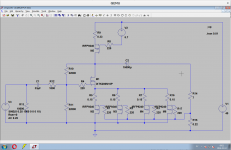
The schematic below is very close to what I hope to build soon.
I will tune the ratios of negative and positive feedback, the total gain of the amp and everything else to suit my taste and needs, but the schematic is a good foundation for PCF Zen amp.
M1 will probably be some other transistor. I used one that is in the standard library in LT-spice. It is close to what I want to use. IRFP150 or IXTH110N10L2 seems like very suitable devices, if I use a simple input JFet buffer.
Cheers,
Johannes
In this simulation I use 4 IRFP9240, not because I would do so in a real amplifier but because the amp behaves much better with a very high gain device in the PCF feedback-loop (the p-channel devices in the bottom of the circuit).
I plan to use an IXTH140P05T from IXYS. It is a very rugged, powerful high transconductance part.
http://ixapps.ixys.com/DataSheet/DS100027C%28IXTA-TH-TP140P05T%29.pdf
The large Ciss should not be any problem since I drive the gate from a 0,22 ohm resistance. Without a gate stopper resitor the feedback would be active to a couple of MHz (and probably oscillate violently).
With a very high transconductance fet with a low Rds-on value the voltage swing in the positive feedback loop is kept low, which also minimizes distortion.
It is also much better to use a very low value sensing resistor. I don't want to add resistance in order to lower resistance. It takes a lot less positive current feedback to overcome the added resistance from a 0,22 ohm sensing resistor then a 1,0 ohm sensing resistor.
The schematic below is very close to what I hope to build soon.
I will tune the ratios of negative and positive feedback, the total gain of the amp and everything else to suit my taste and needs, but the schematic is a good foundation for PCF Zen amp.
M1 will probably be some other transistor. I used one that is in the standard library in LT-spice. It is close to what I want to use. IRFP150 or IXTH110N10L2 seems like very suitable devices, if I use a simple input JFet buffer.
Cheers,
Johannes
Attachments
Based on the lack of interest in this thread, I guess you all understand this already, but for those not well versed in positive current feedback and negative output impedances it should be a quite simple explanation of the function of my simple circuit.
Cheers,
Johannes[/QUOTE]
I do not believe this to be so. For everyone that responds there are many more members and visitors that just read and do not participate in forums. Forums can be intimidating some time.
Cheers,
Johannes[/QUOTE]
I do not believe this to be so. For everyone that responds there are many more members and visitors that just read and do not participate in forums. Forums can be intimidating some time.
+1I do not believe this to be so. For everyone that responds there are many more members and visitors that just read and do not participate in forums.
Hello Circlomanen. I looked at the graph of Typical Output Characteristics, Tc= 25 Celsius for IRFP9240. At an -Id = 1A, and Vds = -10V, this practical operating point sits on top of the Drain-to-Source Voltage [X] axis, The value of -Vgs which sustains this 1A current is not shown. I guessed its value maybe equal to -4.3V for the sake of this discussion. The second graph of Typical Transfer Characteristics for IRFP9240 plots -Id versus -Vgs at -50 Vds at 25 Celsius. It shows that Id = zero Amps when Vgs =-4 V. These combined data by IR say that the amplitude of the PCF sensed signal in your amp is limited to a small value; maybe 0.3Vpp or less as the operating region appears to be non-linear.
However, the Typical Characteristic graphs of IRFP9240 suggest that its Id need to be increased to -3A or higher; say at -10 Vds to give a Vgs = -5V. This -Vgs can handle in a more linear manner the same amplitude PC feedback signal exemplified above.
However, the Typical Characteristic graphs of IRFP9240 suggest that its Id need to be increased to -3A or higher; say at -10 Vds to give a Vgs = -5V. This -Vgs can handle in a more linear manner the same amplitude PC feedback signal exemplified above.


With 4 volts negative voltage on the gate, the IRFP9240 will still sink 4,43 amperes. The Vout is at + 1,57 volts which is the receding transconductance and the resistance of the device at very low voltages drain to source. The IRFP9240 will happily swing 5 volts or so with reasonable low amounts of distortion.
I prefer much more powerful, high transconductance, low voltage parts then the IRFP9240.
Remember that the device is driving a very low impedance load - the source of the N-channel part. There is very little voltage swing. It is mainly controlling current.

Here you can see the green trace that is the positive feedback going into the source pin of the N channel device (you can see the probe in the simulation).
There is 0.1455 volts positive feedback signal for a 11,5 volts output into a 7,22 ohm load.
The IRFP9240 can swing about 6 volts with low distortion in this circuit, even though the rest of the amp can not handle it.
There might be some (small) reduction in distortion to be had by increasing the voltage over the P channel fet, but I doubt it is worth the hassle.
The amp works just as good with the P channel device gate at minus 2 volts for approximately 2 volts less Vds.
Cheers,
Johannes

Here you can see a simulation with 2 volts less Vds.
The probe shows the positive current feedback node between the fets.
There is about 2,5 volts Vds over the P channel fets.
Cheers,
Johannes


Just for the fun of it and as a learning exercise for my self I wanted to do a utterly ridiculous experiment to observe the low voltage behavior of normal cheap IRFP9240/240 switch fets.
Here we have a "classical" push pull source follower stage with a whopping 1,0 + 1,0 volts power supply. It is biased to about 580 mA. There is less then 1,0 volts from drain to source on each device.
It will still swing a total of 0,68 volts without any signs of clipping or even visible rounding of the wave form. At 0,8 volts total output voltage I start to see a faint tendency of rounding of the wave shape.
Cheers,
Johannes
Thank you Circlomanen for the clarification. I need to further study these graphs, and your models. Will any Darlington PNP have a higher transconductance that IRFP9240, and usable in your amp?View attachment 537189
View attachment 537190
With 4 volts negative voltage on the gate, the IRFP9240 will still sink 4,43 amperes. The Vout is at + 1,57 volts which is the receding transconductance and the resistance of the device at very low voltages drain to source. The IRFP9240 will happily swing 5 volts or so with reasonable low amounts of distortion.
I prefer much more powerful, high transconductance, low voltage parts then the IRFP9240.
Remember that the device is driving a very low impedance load - the source of the N-channel part. There is very little voltage swing. It is mainly controlling current.
I would avoid using bipolar devices in general and darlingtons in particular for this amp.
You could (at some small loss of potential voltage swing) use a darlington as a constant current source.
A small cheap fet like a IRF9540 is superior in every way. Remember that you actually want a large Vgs in this circuit. Even though a fet seems reasonably linear at quite small voltages Vds, I don't think it hurts performance to use a 4,5 volts Vgs device.
Cheers,
Johannes
Nono I think this is Very ! interesting
Thanks everyone who cheer me on!
I got the impression that nobody was interested in this. I thought it might not be interesting, it might already be known, tested and disregarded. I have not seen this done this way before, so I just wanted to share my thoughts, ideas, experiments and results here.
The source to source p + n channel fet cascode is not new or novel in any way. It is a basic building block in RF design. Often used as mixers and/or oscillators for both transmitters, regenerative and super-regenerative receivers.
It is a very high gain, linear and controllable compounded device, since it has two high impedance inputs, and the p + n channel fets tend to cancel some of the distortion of each other.
I wanted to test it as a power amplifier and use the most linear input node for the positive feedback.
Cheers,
Johannes
Johannes,
The only question that arise from your work is the following: if the mix of positive and negative feedback is not calculated in a way to eliminate the Rload from the equation, don't you think that what we will obtain is a device that will have an odd behaviour in the frequency domain ? Because what we call Rload is actually a Zload and is frequency dependent.
I was trying, in the F7 thread to come to a solution to modify a pair of F5 boards that I have laying around, although I did not managed yet to convenre to a mathematical solution.
Regards,
Davide
a way to eliminate the Rload from the equation
I am a more hands on kind of guy. I don't really get along that well with math.
An easy way to make the amp load invariant is to adjust the positive feedback resistor in LTSpice and testing different loads. Swap out the 8 ohm resistor load in the simulation to a 4 ohm and then to 16 ohm. With the right balance between positive feedback set by the value of the sensing resistor, and negative feedback, the amp will give the same voltage swing into any load with the same input voltage (within its power limits).
Since LTSpice is only a simulation tool, you will have to do this again with a voltage meter, a signal generator, two power resistors and the real amplifier.
With the right amount of positive current feedback it will give 2,000 volts at 100 Hz over a 10 ohm resistor, then the same 2,000 volts over two paralleled 10 ohm resistors forming a 5 ohm resistor.
If the voltage increases over 5 ohms compared to 10 ohms the amp has a negative output impedance and you should lower the value of the sensing resistor until it is load invariant.
LTSpice is great tool to arrive at a reasonable balance, but you will have to adjust it in real life to compensate for your exact devices.
Cheers,
Johannes
I want to add that a perfectly load invariant amp (infinite damping factor) might not be the best sounding balance with your speakers, cables, crossover, taste and acoustics.
If you go through the pain to design and build something like this then I think you owe it to yourself to actually test some small values of negative output impedance and some small values of positive output impedance. You will be surprised by the results. Some small fraction of negative output impedance can compensate for the resistance in your cables, connectors etc. That is taking the load-invariance a step further.
My BIBs seems to need -1 ohm of output impedance for maximum performance.
Cheers,
Johannes
Last edited:
I just ordered som Cree C3M0065090D SiC mosfets and some IXYS IXTH140P05T and IXTP32P05T devices. I know I want some serious transconductance in the P channel fet, but since I can not make up my mind about how to prioritize different aspects and balance the amp, I had to buy two different P channel parts.
When looking at the curves I believe I getter a better distortion cancellation between the Sic part and the lower transconductance IXTP32P05T part, then between the SiC and the very extreme IXTH140P05T part.
I am very happy about the sudden availability and the rather acceptable price of SiC parts lately. 600pF Ciss makes life a lot easier when implementing some negative feedback to the gate of the SiC device.
Does anybody know if there is some spice models for the Cree SiC devices?
Cheers,
Johannes
I just ordered som Cree C3M0065090D SiC mosfets and some IXYS IXTH140P05T and IXTP32P05T devices.
I will be very interested to see your results with the Cree's. I bought four of these myself, being seduced by their high transconductance and low Ciss, but have never got around to trying them out. My SPICE simulations suggested that this part (and the SiC JFET UJN1208K) can show fairly high levels of higher-order (3rd-6th) harmonics in certain circuits. This could just be a SPICE artifact since Nelson Pass mentioned the UJN1208K as giving comparable distortion figures to the older SemiSouth parts.
Does anybody know if there is some spice models for the Cree SiC devices?
I have attached the C3M SPICE model from Cree's collection of models.
Attachments
Last edited:
- Home
- Amplifiers
- Pass Labs
- Positive Current Feedback simple Zen amp