Thanks for the spice model of the SiC mosfet!
I will test the device in my PCF Zenamp.
------------------------------------------------------------------------------------------------------------------------------
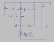
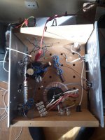
Today I built a new amp. Only one channel as before, but I managed to bolt the devices to two pieces of aluminum plate (heatsinks).
I turned it up side down and used the same IRLB3813 as a load sensing fet instead. I guess (and hope) it is much more linear as a source follower, and especially so at these very low voltages.
I used the power supply from an old amp and got 28 volts from the supply. There is two 4700 uF capacitors followed by a 4 mH inductance (an old coil from a passive crossover) and followed by two 4700 uF and one 1000 uF capacitor.
I use an old IRFP9140 as the main gaindevice. It should be much more linear then the IRLB3813 I used previously.
I can hear that it is happy with a lot more voltage then the old amp. 28 volts instead of 15,5 volts makes a huge difference. The IRLB3813 seems suitable as the buffer for the feedback (or negative source resistor if you want to see it that way). It only takes 2,34 volts which is the Vgs of the device at 1,32 ampere. I like the lower voltage over the device since it does not take as much available voltage away from the rest of the amp.
With only 0,647 ohm sensing resistor it does not have a negative output impedance. When I short a 10 ohm power resistor over the speaker leads while playing a 50 Hz sinus tone at 1,06 volts over my speaker, the output voltage drops to 0,77 volts.
It is very clean, warm, powerful and generally good sounding. I have only played music for half an hour or so, so I can not comment any more then that. It does sound very clean when running a frequency sweep from 10 Hz to 150 Hz at 4,0 volts out.
I will test the device in my PCF Zenamp.
------------------------------------------------------------------------------------------------------------------------------

Today I built a new amp. Only one channel as before, but I managed to bolt the devices to two pieces of aluminum plate (heatsinks).
I turned it up side down and used the same IRLB3813 as a load sensing fet instead. I guess (and hope) it is much more linear as a source follower, and especially so at these very low voltages.
I used the power supply from an old amp and got 28 volts from the supply. There is two 4700 uF capacitors followed by a 4 mH inductance (an old coil from a passive crossover) and followed by two 4700 uF and one 1000 uF capacitor.
I use an old IRFP9140 as the main gaindevice. It should be much more linear then the IRLB3813 I used previously.
I can hear that it is happy with a lot more voltage then the old amp. 28 volts instead of 15,5 volts makes a huge difference. The IRLB3813 seems suitable as the buffer for the feedback (or negative source resistor if you want to see it that way). It only takes 2,34 volts which is the Vgs of the device at 1,32 ampere. I like the lower voltage over the device since it does not take as much available voltage away from the rest of the amp.
With only 0,647 ohm sensing resistor it does not have a negative output impedance. When I short a 10 ohm power resistor over the speaker leads while playing a 50 Hz sinus tone at 1,06 volts over my speaker, the output voltage drops to 0,77 volts.
It is very clean, warm, powerful and generally good sounding. I have only played music for half an hour or so, so I can not comment any more then that. It does sound very clean when running a frequency sweep from 10 Hz to 150 Hz at 4,0 volts out.
Now I use a Caddock MP930-0.75-1% TO-220 power-resistor as the sensing resistor, thereby increasing the R-sense to 0,75 ohm.
There is a wide grin all over my face!!!!! 😀
(Don't use cheap wirewound 5 watt resistors!!!)
There is a wide grin all over my face!!!!! 😀
(Don't use cheap wirewound 5 watt resistors!!!)
https://www.youtube.com/watch?v=CY-n_z_xvNQ
I made a short video of a test I made to hear what a source follower sounds like when running at a very low Vds (Vds = Vgs).
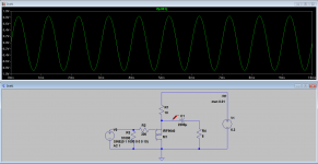
I used an IRF964 in LTSpice instead of the IRF9530 as in the amp in the video, but the difference is negligible.
With only 200 mA quiescent current it sounded ok. Nothing I would use a my main amp. I can't hear any distortion or nastiness, only a correct and plainly sounding amp without any voltage gain. With less then 200 mA I could hear some distortion, increasing fast with less current.
I would call this a torture test, as no sane man would run an IRF953 in a source follower configuration at these low voltages and currents as a real amp to drive speakers.
With 300 mA (or more) it becomes quite enjoyable to listen to. I have had it running in the background for the last hour. I get about 0,5 voltage-swing out of it when driven from the soundcard of my computer (measured by running a 100 Hz sinewave.
It is enough to fill my living room with enjoyable music.
Cheers,
Johannes
I made a short video of a test I made to hear what a source follower sounds like when running at a very low Vds (Vds = Vgs).

I used an IRF964 in LTSpice instead of the IRF9530 as in the amp in the video, but the difference is negligible.
With only 200 mA quiescent current it sounded ok. Nothing I would use a my main amp. I can't hear any distortion or nastiness, only a correct and plainly sounding amp without any voltage gain. With less then 200 mA I could hear some distortion, increasing fast with less current.
I would call this a torture test, as no sane man would run an IRF953 in a source follower configuration at these low voltages and currents as a real amp to drive speakers.
With 300 mA (or more) it becomes quite enjoyable to listen to. I have had it running in the background for the last hour. I get about 0,5 voltage-swing out of it when driven from the soundcard of my computer (measured by running a 100 Hz sinewave.
It is enough to fill my living room with enjoyable music.
Cheers,
Johannes
I increased the gain in the soundsettings and I got 1,2 volts clean voltage swing at 40 Hz with only 300 mA. At 240 mA I could start to hear a some low level harmonics and below 200 mA it starts to distort heavily.
Thanks wdecho!!!
I am also enjoying this. It is a lot of fun to fool around with electronics, and nothing really beats some hands on experience while trying to design and develop amps.
I should not have done this last stupid experiment though...
With 500 mA current and 9,68 volts over the amp (-4,51 Vgs = Vds) it starts to sound quite pleasing. The treble is much improved compared to with only 200 mA (that is a no brainer if any).
I have been sitting in my sofa playing Charles Mingus, Art Blakey and Tom Waits with a big smile in my face.... I am very surprised by the level of sound quality inherent in such a simple circuit. The IRF9530 is a nice linear device with quite low Ciss of only 860 pF.
If used together with two Beyma 12P80Nd per channel in a very large BIB (extreme efficiency) I would probably be satisfied with this amp. I am actually considering building a stereo amp based on this design. I guess one ampere of current and three 22 ohm power resistors per channel would make a great little amp for my computer speakers. A 12 volt DC output switched powersupply is cheap..... I have the IRF9530 and the heatsink....
I am having lots of fun while waiting for my Cree SiC fets. They have arrived in Stockholm today....
Cheers,
Johannes
I think there is some real inherent value in testing these basic sub-circuits.
In testing and listening to a simple low voltage Vgs=Vds it is easy to get an understanding for what makes it sound in a special way. It is easy to see what limits the performance and how to maximize performance.
I am amazed by the level of sound quality that is available from a single mosfet, once it has some current to work with. As Nelson Pass often points out, these cheap switchfets needs some real current to sound good. There are few as nasty sounding devices as a current-starved IRFPXXX. Running two IRFP150 in an lean class ab output-stage with lots of negative feedback is probably the best way to create a horrible "angle grinder against large sheets of steel" music experience.
The IRF9530 sounds reasonably clean but very plain and dull at 300 mA. At 400 mA it is listenable. At 500 mA it is enjoyable. At 1,0 ampere it sounds very clean, effortless and "alive". No listening fatigue. Nothing hard or nasty. Just enjoyable music being reproduced in an effortless and engaging way.
I would love to hear my IXUS devices in this simple test-amp with 5 ampere flowing through them. With only 5 volts Vds there is no problem running a good amount of current through it without overheating it.
In building a more complex amplifier, I think it is important to evaluate every sub-circuit separately to get a good understanding for every parts potential contribution to the whole.
I have been building and using simple Zen amps since 2001. This low voltage Vds source-follower was new to me. The experiment I made today reinforced (with vigor) my position that it does not need a greater voltage for the few fractions of a volt withing the positive feedback loop. If I can run a low distortion 1,2 volt 40 hz sinewave into a reactive speaker with it, then it will sound great in a tight low voltage feedback loop.
Cheers,
Johannes
Johannes,
I like your thread very much! Perhaps I'll build one myself to one of your examples. 😉
A little question: to which configuration refers your latest post?
A one FET, two FET or three FET configuration?
Other questions: In the feedback circuits a resistor (about 1 Ohms) is used for the feedback. Is the value of this resistor dependant on the actual load?
What would be the influence of a cheap wire-wound resistor in that place?
Regards,
Edwin
Is the value of this resistor dependant on the actual load?
What would be the influence of a cheap wire-wound resistor in that place?
The value of the sensing resistor (1,0 to 0,22 ohm in different amps) is dependent on gain, load and how much positive current feedback you want or need. A higher resistor value will lower the output impedance of the amp - even to negative values of output impedance.
This needs some experimentation and some patience to optimize.
There is certainly a lot of math-heavy ways to optimize this, but since I don't get along with math, I prefer to do it the old fashioned way (with a screwdriver and a trim-potentiometer).
When I used a cheap 5 watt ceramic wire wound resistor the amp sounded harsh and edgy. I guess the added inductance in the positive feedback made the amp unstable and prone to spurious oscillation.
With a nice low inductance Caddock TO220 power resistor the amp sounded like a nice single ended class A amp should do.
Cheers,
Johannes
Tack Tord Nillson!!! 🙂
I want to point out that we have not explored any of the fun advanced options that this dual feedback loop design offers.
With a very linear and powerful positive feedback loop controlling the output impedance you have a lot of options for filter functions. This will give frequency dependent variations in gain, output impedance and more, enabling speaker and acoustic compensating EQ and a fine-grained control of the driver, increasing and decreasing Qes at any frequencies to shape the response of the speaker to your needs. This a great tool in designing loudspeakers, since you can use a very powerful high Bl driver like a B&C IPAL-18 in a BIB and shape the response curve with the output impedance of the amp and some active EQ.
The most obvious one is to add a single resistor and a single capacitor to the positive feedback (gate of the sensing device - the potential negative source-"resistor") to form a lowpass filter. This will gradually change the output impedance from negative values at low frequencies to positive values at higher frequencies.
It would be very simple to create a bandpass filter in the positive feedback loop to have a very low output impedance centered around the Fs of the driver or the resonant frequency of the basreflexbox, etc... There are endless possibilities. If combined with a very linear and simple gainstage with a inherent high stability the world of fun audio experiments is yours to explore.
Think of the rich possibilities of advanced and fine grained speaker and amp interface adjustments and tunings you can have.....
Cheers,
Johannes
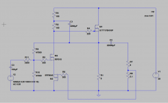
Here is a very simple two stage variation of the same amp. I have basically added a output buffer/source-follower to increase gain and lower the open loop output impedance (before adding PCF).
With only 0,1 ohm sensing resistor and a very powerful IXYS mosfet as source follower I get a negative output impedance. I can't calculate how low it is, but the output voltage will increase with lower resistance load according to the simulation.
Might be something to use if you primarily want to drive difficult subwoofers.
The source follower can have a constant current source, but I wanted to keep it simple for clarity. I like using simple power resistors instead of active constant current sources. It keeps the amp simple, stable and much more fool proof.
Power resistors are cheap compared to massive heatsinks.
Just an idea, based on the PCF-Zen amp, for anyone who wants to fool around it.
Cheers,
Johannes
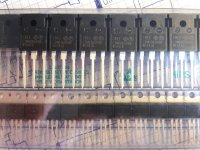
Please excuse my poorly restrained enthusiasm!
Cree creates happiness and glee... 😀
This is going to be interesting. How will a SiC fet react to some positive feedback.
I have seen that positive current feedback supercharges the innate character of the gain device, which is not very strange considering that you are feeding a signal with the character of the gaindevice superimposed, into the gaindevice again.
The IRLB3813 sounds very powerful and aggressive by it self, but with some positive current feedback it sounded like a raging bull on steroids.
A IRFP9140 is a quite nice, plain device with a relaxed sound character. With PCF it did not change much. It sounds nice and relaxed until the PCF is turned up to near oscillation where it sounds hollow, distorted and metallic.
I hope some PCF can lift the SiC fet slightly. I don't expect SIT character from it. It does have normal penthode curves like most mosfets.
Cheers,
Johannes
Last edited:
https://www.youtube.com/watch?v=9Sy-sXENDgg&feature=youtu.be
I have tested the IXYS IXTP32P05T P channel Trench power mosfet in the excact same cheap and crude setup as I did with the IRF9530.
I will probably never use an IR part again..... (maybe as regulators, switches and stuff like that).
The difference is staggering. When run with very low voltage and current it starts to distort as expected, but much smoother with much less offensive distortion. Much lower order harmonics. It just very smoothly starts to distort in a very gentle and polite way. The Vgs changes very little once out of the sharp turn-on region. The device has much more transconductance at low voltages and currents then a IRF950, IRFP9140, IRFP150, IRFP250 and some other IR devices I tested over the years.
The IXYS part sounds better with 200 mA current then the IR part sounded with 500 mA. The IXYS part does not change character with different amount of current in the same way as the IR part does. It is soooo smooth and nice!!!
@tordnilsson:
I get approximately 3 watts into 8 ohms from my 28 volts supply, 1,3 ampere of current and the devices used.
You loose a couple of volts due to the Vds of the bottom PCF fet.
It is easy to scale to a couple of hundred watts if you got the rather substantial hardware needed to supply power and cool the devices.
A few of these: http://ixapps.ixys.com/DataSheet/DS100196(IXTN110N20L2).pdf
could be nice. I recommend watercooling. 😀
Cheers,
Johannes
Better yet: liquid hydrogen.....😀I recommend watercooling. 😀
And while you are at it you can use the same liquid hydrogen to cool your superconducting electromagnets for your Feastrex full range speakers...
You don't want to skimp on BL... 😀
You don't want to skimp on BL... 😀
- Home
- Amplifiers
- Pass Labs
- Positive Current Feedback simple Zen amp
