SIMPLICITY = RELIABILITY, USE YOUR 2030/2050 TO DRIVE A PAIR OF TIP35/36'Cs.
Run a heavy current transformer as found in nad or pioneer retro, A FEW 10000UF CAPS IN THE PSU and blow the place apart, guaranteed to rearrange your ornaments.
Use a thermal switch to pull the fan in at 60-80 degrees and away you go.
I HAVE PUSHED THE ST MICRO 35/36C'S WAY OVER 100V AND THEY ARE STILL GOING
Judging from some of the Pictures, and previous mouser BOM links; it looks like like some people used 7mm resistor length, and just bend tighter to the body. I've reached another point of indecision. I guess I'll make a list of the ones I can't find in a smaller length, and see where I stand.
top pic in post1984
Resistor R51 looks like a 600mW in 0.4" pad pitch
R40 looks like the bigger 500mW in a 0.5" or 0.6" pad pitch.
R13 is a tiny resistor in the standard pad pitch of 0.4"
A 6.5mm, or 6.8mm, body length fits comfortably into 0.4" (10.16mm) pad pitch.
Check you pad pitch for the standard resistors.
Resistor R51 looks like a 600mW in 0.4" pad pitch
R40 looks like the bigger 500mW in a 0.5" or 0.6" pad pitch.
R13 is a tiny resistor in the standard pad pitch of 0.4"
A 6.5mm, or 6.8mm, body length fits comfortably into 0.4" (10.16mm) pad pitch.
Check you pad pitch for the standard resistors.
Last edited:
https://www.seielect.com/Catalog/SEI-RNF_RNMF.pdf
for the 1/4 watt the stackpole rnmf are tiny. I believe panasonic also does a miniature line.
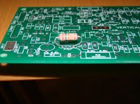
Or You can just do as in the attached photo (extreme example for show) and not worry too much.
E
for the 1/4 watt the stackpole rnmf are tiny. I believe panasonic also does a miniature line.
Or You can just do as in the attached photo (extreme example for show) and not worry too much.
E
Attachments
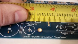
Assuming not too much parallax, I see >>5/16ths and <3/8thsThat's what I'm measuring center-center. Looks like 5/16 (.3125) for R51
It looks like ~9mm (0.354") to my eyes. Maybe he set the layout to 0.35"
A bit small for 6.8mm body resistors.
Would work with 6mm bodies.
Assuming not too much parallax, I see >>5/16ths and <3/8ths
It looks like ~9mm (0.354") to my eyes. Maybe he set the layout to 0.35"
A bit small for 6.8mm body resistors.
Would work with 6mm bodies.
You are correct, I mis-spoke. It is pretty much right in between 5/16 and 3/8.
https://www.seielect.com/Catalog/SEI-RNF_RNMF.pdf
for the 1/4 watt the stackpole rnmf are tiny. I believe panasonic also does a miniature line.
Or You can just do as in the attached photo (extreme example for show) and not worry too much.
E
Thanks
FYI; for those interested: "Resistor Pitch Pad Measurements"
R23, R27, R32, R33, R37, R42-46 - All measure 0.500 (1/2) (12.7mm)
R38-41 - Measure 0.594 (19/32) (15mm)
R36 - Measure 0.656 (21/32) (16.5mm)
R49-50 - Measures 0.719 (23/32) (18.3mm)
All other resistors (except trimmers) measured 0.344 (11/32) (8.75mm)
Note: I used a precision ruler (in 64th's), and had only 2 glasses of red wine.
Measurments should be accurate.
Another FYI:
Mouser shows all 1/2W MFR series Yageo resistors at 2.4mm length, the data sheets shows 6.3mm. I believe they were looking at the diameter.
Mouser shows all 1/2W MFR series Yageo resistors at 2.4mm length, the data sheets shows 6.3mm. I believe they were looking at the diameter.
Okay, I think I've decided to go with the 1/2 watt MFR Yageo resistors for most of them...
It allows me to use 1/2 watt 1% resistors (which isn't so important for this project, but allows my stockpile to be a little more flexible in the future, I think). These resistors are smaller than some of the suggests (6.3mm Vs. 6.5mm for the 0.344 pads), metal-film Vs carbon film, and 1% vs 5%. I am starting to think that I am overthinking this way too much.
Any last objections?
If your resistor bodies are a bit too long to comfortably fit the pad pitch on the pCB, you can use the double bending shown in post 2006. (That looks like an 8mm body into a 5.08mm pitch, quite extreme).
Raising the resistors above the PCB does give the advantage of leaving a place to hook on a test probe for safer measuring during the test phase.
Raising the resistors above the PCB does give the advantage of leaving a place to hook on a test probe for safer measuring during the test phase.
Raising the resistors above the PCB does give the advantage of leaving a place to hook on a test probe for safer measuring during the test phase.
"Always look on the bright side of life" . I don't know why that reminded me of Monty Python
Picked up 6 feet of enameled 18 GA copper wire today while I was out of town! I'll probably do a Mouser order tomorrow or the next day for the badgers. I was gonna order stuff for the PSU, etc. But will probably do that later. Still have a few decisions to make.
Also picked up a resistor bin with 64 drawers, and re purposed an old door into a work table. I officially have a "shop" in my basement now lol.
Also picked up a resistor bin with 64 drawers, and re purposed an old door into a work table. I officially have a "shop" in my basement now lol.
I covered my old door in a sheet of 1/8" hard board.
Replaceable when it becomes too damaged.
Replaceable when it becomes too damaged.
I covered my old door in a sheet of 1/8" hard board.
Replaceable when it becomes too damaged.
Good idea! That gives a better surface too.

Not pretty, but functional for now. Will re-assess when we renovate the house in the spring/summer!
If you work like many of us, you won't see the bench top for long anyway. It'll be buried in tools and parts.
- Home
- Amplifiers
- Solid State
- diyAB Amp The "Honey Badger" build thread