Thanks heaps for the responses guys, I definitely had a bit of a brain fart there in not realising about the bi-polar thing. The main thing which threw me with the capacitor was the fact that the legs were a different length, which I guess is irrelevant in this case.
Also thanks AndrewT, I must be starting to understand electronics a bit better since most of what you said is actually starting to make sense to me!
Also thanks AndrewT, I must be starting to understand electronics a bit better since most of what you said is actually starting to make sense to me!
So I've made a bit more progress but I have few more questions about wiring etc. Because most of the stuff I've found on the forum has been related to older versions of boards I just want to make sure this is right.
I've just omitted the other channel for the sake of simplicity. I'm also still reading up on grounding so haven't worked all of that out yet.
The other thing I wanted to check is that I needed to install the jumper next to C1? I think I remember reading something about this before but just wanted to make sure.
Attachments
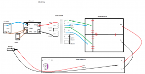
You have omitted the PSU to Amplifier zero volts wire.
RCA Out needs to be relabled to speaker output.
RCA Out needs to be relabled to speaker output.
Thanks mate, so this is probably a daft question but where do I get the psu to amp 0v from?
I didn't draw it on the picture but I was going to wire a TS jack with the tip going to 'IN' and the sleeve going to '0V', which is possibly wrong?
Cheers
I didn't draw it on the picture but I was going to wire a TS jack with the tip going to 'IN' and the sleeve going to '0V', which is possibly wrong?
Cheers
Do you have the schematic for the "Universal Psu v3"?Thanks mate, so this is probably a daft question but where do I get the psu to amp 0v from?
.................
Do you have the PCB?
PSU zero volts should be shown on both.
Last edited:
TS jack is a Tip/Sleeve plug.............I didn't draw it on the picture but I was going to wire a TS jack with the tip going to 'IN' and the sleeve going to '0V', which is possibly wrong?...............
Why should that replace the RCA? and why should that connect to the speaker output?
Sorry, think we got our wires crossed there.
I'm probably planning on having 1/4" TS in (depending on what I work out with my question in the preamp thread), and RCA out.
I was going to wire the TS to the IN and 0V euroblocks, and have the OUTPUT and SPK GND going to the RCA.
I'm probably planning on having 1/4" TS in (depending on what I work out with my question in the preamp thread), and RCA out.
I was going to wire the TS to the IN and 0V euroblocks, and have the OUTPUT and SPK GND going to the RCA.
Do not use an RCA for speaker output.
Use conventional speaker terminals/socket/connectors.
Use conventional speaker terminals/socket/connectors.
RCA Out needs to be relabled to speaker output.
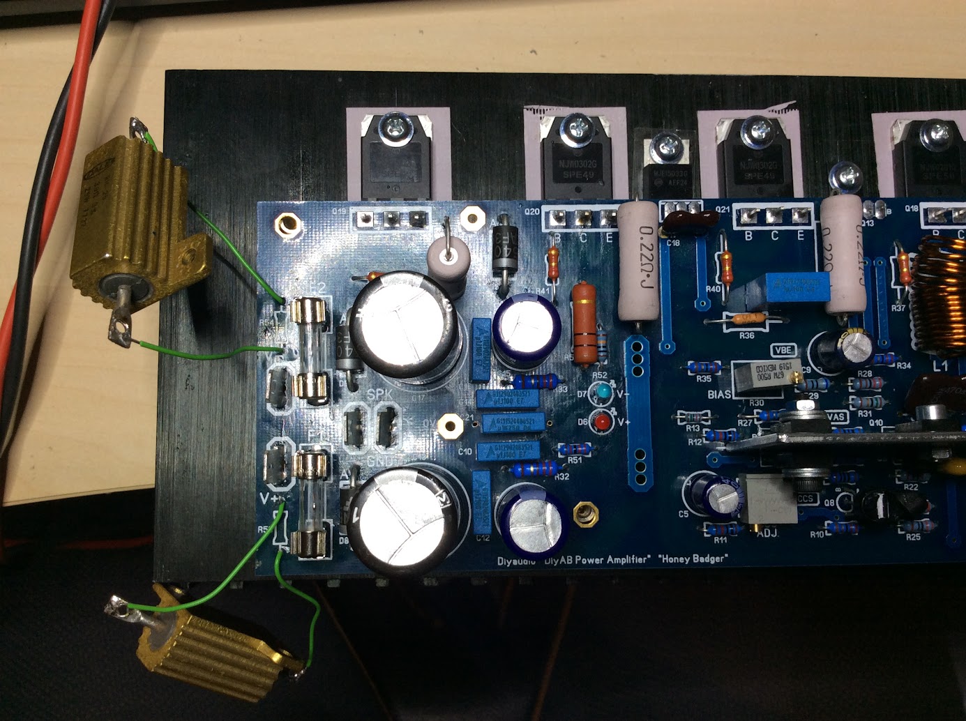
Hi, trying to boot up one of these boards but I have some troubles with fuses blowing and R53 and R54 catching fire. So finaly got me a couple of those yellow 25W.
Bias is put to maximum. I dont remember correctly after discussing with myself of witch, one of the leds flares imidiatly, I think blue (not sure anymore after turning the board every witch way). The other led is not lighting as far as I could tell.
No leak to ground earth through any transistors and yes there are plastic between the bolts,, and no, no meassurable resistance between anything to earth ground.
Hi, trying to boot up one of these boards but I have some troubles with fuses blowing and R53 and R54 catching fire. So finaly got me a couple of those yellow 25W.
Bias is put to maximum. I dont remember correctly after discussing with myself of witch, one of the leds flares imidiatly, I think blue (not sure anymore after turning the board every witch way). The other led is not lighting as far as I could tell.
No leak to ground earth through any transistors and yes there are plastic between the bolts,, and no, no meassurable resistance between anything to earth ground.
You need to build a bulb limiter before you burn your house down. You shouldn't need those big aluminum case resistors either.
You need to build a bulb limiter before you burn your house down. You shouldn't need those big aluminum case resistors either.
I probably should not, but it's what I had left after burning up everything else up while testing. We can agree on that part yes ;D
You should start by double checking if your output transistors are installed in the correct positions. You have some serious current going on there. The bulb limiter will stop anything from burning up if you make a mistake like that. Powering it up without would almost certainly destroy the output devices if they are installed in the wrong position.
An externally hosted image should be here but it was not working when we last tested it.
https://m.flickr.com/#/photos/54959803@N06/24484091204/
🙂
Last edited:

Hi, trying to boot up one of these boards but I have some troubles with fuses blowing and R53 and R54 catching fire. So finaly got me a couple of those yellow 25W.
Bias is put to maximum. I dont remember correctly after discussing with myself of witch, one of the leds flares imidiatly, I think blue (not sure anymore after turning the board every witch way). The other led is not lighting as far as I could tell.
No leak to ground earth through any transistors and yes there are plastic between the bolts,, and no, no meassurable resistance between anything to earth ground.
I don't see any insulating washers on your driver transistors, under the head of the screw. That would short your rails together via the heatsink and mounting screws.
Hi, trying to boot up one of these boards but I have some troubles with fuses blowing and R53 and R54 catching fire. So finaly got me a couple of those yellow 25W.
Bias is put to maximum. I dont remember correctly after discussing with myself of witch, one of the leds flares imidiatly, I think blue (not sure anymore after turning the board every witch way). The other led is not lighting as far as I could tell.
No leak to ground earth through any transistors and yes there are plastic between the bolts,, and no, no meassurable resistance between anything to earth ground.
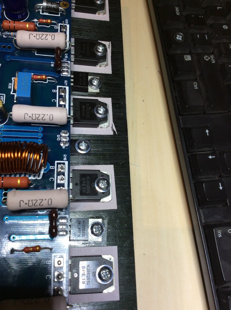
It looks like there is a gap(loose transistor) on the VAS in pic 2
The one on bottom of the picture.
There is; and no shorting between any of those connected to the heatsinkI don't see any insulating washers on your driver transistors, under the head of the screw. That would short your rails together via the heatsink and mounting screws.
Sent from my GT-I9305 using Tapatalk
I see that now I cannot open or watch the photos so here is the direct link to the album
https://goo.gl/photos/GdJ1cQuH4wroG62E6
https://goo.gl/photos/GdJ1cQuH4wroG62E6
It looks like there is a gap(loose transistor) on the VAS in pic 2
The one on bottom of the picture.
yes, but nothing very dangerous there, bias is set to zero and the **** just doesn't work ;D
- Home
- Amplifiers
- Solid State
- diyAB Amp The "Honey Badger" build thread