Thank you MASantos.
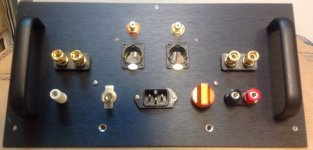
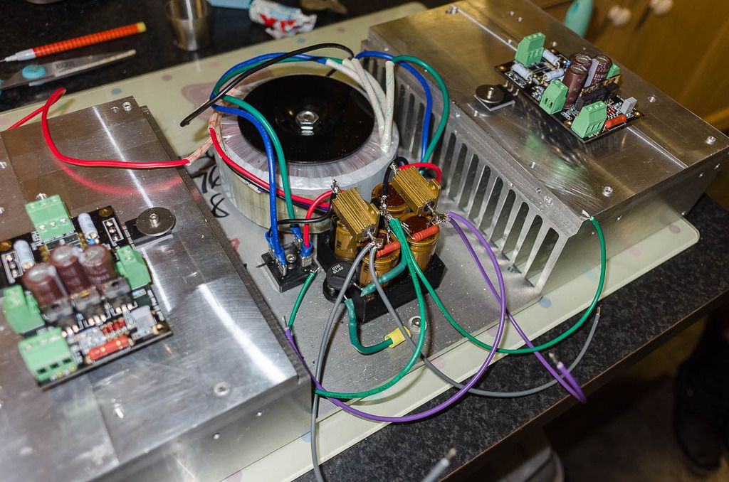
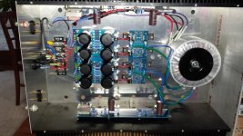
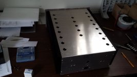
The central pcb is of my own design (unfortunately the proto board had a few small errors) and is used to control the soft start, loudspeaker protection (with power on/off muting) and indicator leds. It also has the dc removal filter for the main toroidal transformers. The controller is a simple state machine based on old but robust 4000 series CMOS gates and counters - a partial schematic is attached.
View attachment Amp Control V2 Schematic p1.pdf
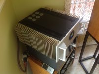
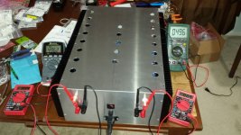
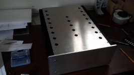
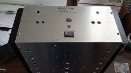
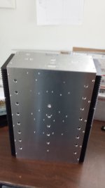
All the mains power components are housed under the aluminium screen - prevents me being zapped in case I get careless.
regards,
Rick
The central pcb is of my own design (unfortunately the proto board had a few small errors) and is used to control the soft start, loudspeaker protection (with power on/off muting) and indicator leds. It also has the dc removal filter for the main toroidal transformers. The controller is a simple state machine based on old but robust 4000 series CMOS gates and counters - a partial schematic is attached.
View attachment Amp Control V2 Schematic p1.pdf
All the mains power components are housed under the aluminium screen - prevents me being zapped in case I get careless.
regards,
Rick
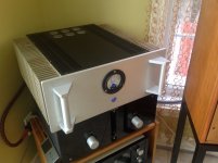
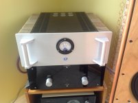
Pictures of my latest PassLabs amp. It took me three months to complete this monster. 😀
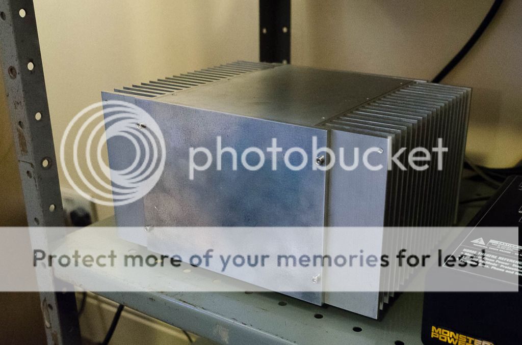
It started with the recycled heatsink I had for years now, and I was waiting to put them to good use. I still have ten of them 😉
They weight a ton. The base plate is 3/4 inch aluminum and they were used on 100W continuous RF amplifiers. I was expecting them to do a fine job on this Class-A amp and I was right.
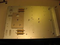
The base plate that we don't see, or care is done using a3mm aluminum plate recycled from a rack mounted supply. It was bendings in it, is tough, very rigid and make for a very stable base for the amp.
The base plate was cut to size and both heatsinks are screwed to it using their thick plate.
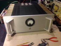
To complete the amp I bought HiFi2000 spare parts for the rear and top plates, and the 10mm brush aluminum front plate. I also bought the optional handles. This heavy amp is easier to move around with the rear and front handles.
The end result is kind of macho, industrial look. Some like it, some not.
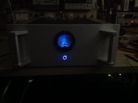
In real it is imposing and understated. I like it.
The amp sounds very good, but it still weight a ton 😉
It started with the recycled heatsink I had for years now, and I was waiting to put them to good use. I still have ten of them 😉
They weight a ton. The base plate is 3/4 inch aluminum and they were used on 100W continuous RF amplifiers. I was expecting them to do a fine job on this Class-A amp and I was right.
The base plate that we don't see, or care is done using a3mm aluminum plate recycled from a rack mounted supply. It was bendings in it, is tough, very rigid and make for a very stable base for the amp.
The base plate was cut to size and both heatsinks are screwed to it using their thick plate.
To complete the amp I bought HiFi2000 spare parts for the rear and top plates, and the 10mm brush aluminum front plate. I also bought the optional handles. This heavy amp is easier to move around with the rear and front handles.
The end result is kind of macho, industrial look. Some like it, some not.
In real it is imposing and understated. I like it.
The amp sounds very good, but it still weight a ton 😉
Attachments

Last edited:
The amp sounds very good, but it still weight a ton 😉
Looks very nice!
Which amp is in it?😀
Special 😉 It started as an Aleph-X years ago, and then was upgraded countless time. Lets say it is like a mix of UGS UP amplifier, XA.5 and XA.8 with custom supply, power-on circuit, etc...
It is entirely hand made, pcb, some point to point wirings, and I did the complete mechanical assembly, and countless test at different bias until I got it right, at least to me.
It is probably cheaper, faster and much easier to buy an original used XA.5 amp than to try to build one, but it was fun!
It is not a beginner project for sure!
Here is my latest amplifier. A Mini-Aleph, recycled heat sinks from a variable speed drive for a 3 phase motor.
pretty nice
though , good praxis is to have stubs for pcbs , not trusting just mosfet pins to carry them
though , good praxis is to have stubs for pcbs , not trusting just mosfet pins to carry them
pretty nice
though , good praxis is to have stubs for pcbs , not trusting just mosfet pins to carry them
I have drawn them up, I just need to 3d print them, every project it a work in progress 😀
Is that also how you mounted the caps, 3D printed clamp? Very cool!
Yes and the feet, I built a 3d printer so try and use it where I can. I got a bit ahead of myself and forgot the pcb supports.
F6 Mosfet
Here's my new F6 mosfet. Sounds great. Definately worth the time and expense.
Here's my new F6 mosfet. Sounds great. Definately worth the time and expense.
Attachments


Wonderful work, Vince! How large is the chassis and how hot does it get?
Cheers,
Dennis
Thanks marra, surprised at the sound with mono power supply.
Chassis inside is 21x12x6 inches. Bias at .63v across the source. 47 ohm resistor, it's warm. I think I can go higher, but I don't know what's reasonable. I can measure mosfet cases and do hand test, but not sure it's really it's necessary or if I'll get better performance. Sounds amazing out of the gate...
Is it voltage drop div by source resistor value = current?
Thx,
Vince
- Home
- Amplifiers
- Pass Labs
- Pictures of your diy Pass amplifier