I am using a generic three way crossover from Jaycar, I use this amp for all multimedia, last night my wife was watching TV and said was having trouble hearing the voices and that is the problem the midrange is not prominent enough to balance out the lower and higher frequencies in my system.
This is very important info!
The generic cross-over lead me to think the loadspeaker first it's not perfectly balanced.
I know this is a serious problem since my previous loudspeakers (modded Infinity Alpha 40) were not balanced too and it was a PITA selecting parts.
In such context the small imbalance of the Caddocks could be magnified.
So, once again, I suggest you to follow my advice.
And at the same time, like Tom Suggested, you should try the amp with other speakers, don't you have a friend which could lend his loudspekers for a day or two?
anyhow I will probably shelve my refs for a while I don't have time right now my 4 month old son is sick
I'm really sorry to read that 🙁
I hope he feels better soon.
I am still a bit disappointed I spent more time and money on this amp than any other, but for those of you are happy, don't let my experience deter anyone from trying them.
You shouldn't, the amp, as is now, is a great performer as assessed by more than an hundred builders... I would consider changing loudspeakers or at least giving them a crossover designed for their drivers.
When I've built my first original My_Ref it became obvious that a lot of previous choices and bought devices should be changed and/or upgraded.
The final result will be astounding, in my case it was so.
Hi everybody,
Finally I have finished the FE V7 board assembly (Thanks again Dario for the complete service 🙂 )
I have made tests on the board, and the results are very nice and clean. This version of the FE board measures very close to what I had seen testing my original Penasa Myref-Evolution units.
Bravo, Dario!
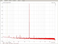
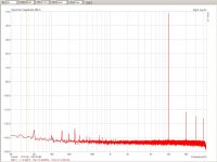
In the pics there is the output at 5W, at 1kHz and 10kHz.
In the PDF there a lot more additional tests.
Enjoy
Finally I have finished the FE V7 board assembly (Thanks again Dario for the complete service 🙂 )
I have made tests on the board, and the results are very nice and clean. This version of the FE board measures very close to what I had seen testing my original Penasa Myref-Evolution units.
Bravo, Dario!
In the pics there is the output at 5W, at 1kHz and 10kHz.
In the PDF there a lot more additional tests.
Enjoy
Attachments
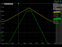
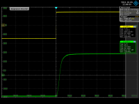
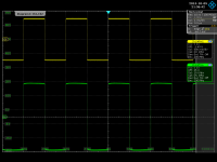
Additionally, here are some time domain tests, showing square wave response on 6.8ohm load, -yellow trace always the generator, -green is output
-1. 1kHz square at close but below to 50Vp-p output
-2. close-in zoom of the same
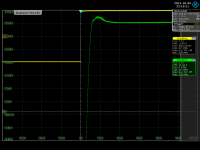
-3. clipping at 27V peak, 54Vp-p
-4. showing the behaviour when getting out of clipping, almost zero sticking, as visible
To note that during these tests the dissipated power was such that at a certain point my poor test resistor had just dis-soldered itself with a soft plop sound..
(I used to just hang it in the air below the setup)
Ciao, George
-1. 1kHz square at close but below to 50Vp-p output
-2. close-in zoom of the same
-3. clipping at 27V peak, 54Vp-p
-4. showing the behaviour when getting out of clipping, almost zero sticking, as visible
To note that during these tests the dissipated power was such that at a certain point my poor test resistor had just dis-soldered itself with a soft plop sound..
(I used to just hang it in the air below the setup)
Ciao, George
Attachments
Last edited:
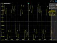
For fun, this is the Dynamic InterModulation test waveform, the one which the amplifier had managed to follow (at 5W output power) with
DIM=0.00047% fidelity
(3,18kHz square + 15kHz pure sine, 4:1 ratio)
DIM=0.00047% fidelity
(3,18kHz square + 15kHz pure sine, 4:1 ratio)
Attachments
Last edited:
Another 'quote' from the pdf measurement file above:
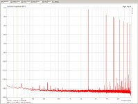
The distortion vs. frequency sweep.
Measurement setup / sound card bottom line is flat around THD=0.00015%, ~up to 20kHz.
As visible, the amplifier distortion at low frequencies is dissolving in the measurement background, but at 10kHz it is very cearly standing out.
The distortion vs. frequency sweep.
Measurement setup / sound card bottom line is flat around THD=0.00015%, ~up to 20kHz.
As visible, the amplifier distortion at low frequencies is dissolving in the measurement background, but at 10kHz it is very cearly standing out.
Attachments

Changed caddock resistors as per your suggestion and wow the amps sound much better clear and balanced amazing difference,
thanks clave
thanks clave
Changed caddock resistors as per your suggestion and wow the amps sound much better clear and balanced amazing difference,
😉
Did you replaced also the 50R MP915?
If you want more, replace FMs with LZXs, change the KOA SPR2 with a KOA MF, as per the updated BOM.
thanks clave
You're welcome 🙂
Hi everybody,
I have made tests on the board, and the results are very nice and clean. This version of the FE board measures very close to what I had seen testing my original Penasa Myref-Evolution units.
Bravo, Dario!
Joseph,
Thank you for sharing your test results. Back in the tuning and "release candidate" days of the FE development, everyone wanted to see testing like this, but no one had the tools to provide the kind of information that you did. Fantastic.
Jac
Yes replaced 50ohm and today i got lxz caps if i get time put in tonight
😉
Did you replaced also the 50R MP915?
If you want more, replace FMs with LZXs, change the KOA SPR2 with a KOA MF, as per the updated BOM.
You're welcome 🙂
Hello,
i have some spare 470uF brown Silmic IIs that i meant to use as C1 and C2 caps. Are LXZs actually better in that position or were they chosen for their lower price?
More: i have some spare Vishay wirewound resistors i was thinking would be ok for some positions (R11, R101/201, R104/204). I ususally find them good and neutral sounding.
I can't see any wirewound in your BOM... do you find they're not good sounding enough compared to KOA and Vishay metal films?
Thanks in advance
Hello,
i have some spare 470uF brown Silmic IIs that i meant to use as C1 and C2 caps. Are LXZs actually better in that position or were they chosen for their lower price?
More: i have some spare Vishay wirewound resistors i was thinking would be ok for some positions (R11, R101/201, R104/204). I ususally find them good and neutral sounding.
I can't see any wirewound in your BOM... do you find they're not good sounding enough compared to KOA and Vishay metal films?
Thanks in advance
LZX have been selected because they sound better!
BTW in C1 and C2 should be used low-esr caps.
Never tried wire wound resistors on the My_Ref apart the output resistors.
I would suggest you to stick to the BOM
For whom is interested I've started a new GB for v1.6 boards:
http://www.diyaudio.com/forums/grou...ion-gb-eight-run-v1-6-boards.html#post4624023
http://www.diyaudio.com/forums/grou...ion-gb-eight-run-v1-6-boards.html#post4624023
For whom is interested I've started a new GB for v1.6 boards:
http://www.diyaudio.com/forums/grou...ion-gb-eight-run-v1-6-boards.html#post4624023
just a heads up: C13 is obsolete and unavailable from mouser
just a heads up: C13 is obsolete and unavailable from mouser
Just replaced it in BOM with CDE940C, they should be pretty similar.
BTW I would use the suggested best part, Mundorf MCAP Supreme.
Joseph,
Thank you for sharing your test results. Back in the tuning and "release candidate" days of the FE development, everyone wanted to see testing like this, but no one had the tools to provide the kind of information that you did. Fantastic.
Jac
Thank you Tom, and pardon me, been absorbed in real life businesses..
Yes, I woke up a bit late.. Dario had told me the same..
My only excuse is that I had been lazy/ but cautious as well to go and tweak my sound card. I'm always on the opinion that a less spectacular but still working device is still much more worthwile than a not working, 'upgraded' device..
So I decided on the upgrade act only last year; and the much better high frequency behaviour obtained was crucial to be able to proceed onto testing real life devices, like the FE, for example.
Ciao, George
First of all, Pardon me, Jac, obviously I meant to answer to You!!
Then, the slew rate: let's have a better look at slide 2 in post #2304 :
(the zoomed in ~full swing output)
It is visible that the signal swings from -~20V to +15V in about 3 useconds; (this is the slew-limited fast part)
That is 35V swing/3useconds = 11.6V/useconds. ~~, to be precise.. 🙂
Ciao, George
Last edited:
- Home
- Amplifiers
- Chip Amps
- My_Ref Fremen Edition - Build thread and tutorial