The slew rate is measured from 10% to 90% of the full signal swing, i.e. from -22.5V to +22.5V of the 50Vpp. Is it from -20V to +20V?First of all, Pardon me, Jac, obviously I meant to answer to You!!
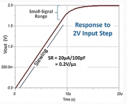
Then, the slew rate: let's have a better look at slide 2 in post #2304 :
(the zoomed in ~full swing output)
It is visible that the signal swings from -~20V to +15V in about 3 useconds; (this is the slew-limited fast part)
That is 35V swing/3useconds = 11.6V/useconds. ~~, to be precise.. 🙂
Ciao, George
The time for this swing will be around 5us to 6us and equates to ~ 8V/us to 9V/us
No precision about it.
from Slew RateThe rise time usually measured between 10% and 90% of the amplitude.
Last edited:
Just replaced it in BOM with CDE940C, they should be pretty similar.
BTW I would use the suggested best part, Mundorf MCAP Supreme.
As atupi said, for those who want the Vishay V-735P, check other sources because they will be available for a long time. They are not that obsolete and Mouser tends to be the first supplier to dump obsolete parts because they have so much turn over.
If you are curious about lower cost C13 cap choices, please read my post on page 222, post 2215. In it, I recently compared several of these alternatives.
I agree with Dario that the Mundorf MCAP Supreme is a worthwhile step for this amp.
At a lower price point, the Cornell Dubilier 940C and 942C have different character from each other and the Vishay. The 940C is very neutral but a little less dynamic than the Vishay or especially the Supreme. The 942C is not quite as neutral as the Supreme, but has excellent dynamics.
When I reviewed them, I could only buy a 1.2 kV version of the 942C. Now, Mouser has a 600 V version available for about the same price as the 940C. It is smaller than the 1.2 kV version, so it fits the board better. If you are like me and appreciate the stronger dynamics, and if the lower voltage version keeps this character, then the 942C would be an interesting choice.
Jac
Last edited:
Dear Andrew,
"The slew rate is measured from 10% to 90% of the full signal swing"
Hm, I think you have just defined the method of measuring the ! rise time ! of a signal, in general.
(more explicitly, the 10%-90% sub- category of it, because there are more)
In which, for example in our case, there are a lot of factors mixed in:
amplifier slewing speed; amplifier GBW (small signal bandwith); amplifier input filter BW; etc.
To shed more light on what I'm referring to -- is better described here:
Slew Rate?the op amp speed limit | EDN
Explicitly, I was talking about the same differentiation shown in figure 1, 'slewing part' of the output rise time and the 'small signal range' of final approach to the full output.
Just my two cents
Ciao, George
Attachments
Last edited:
And something went pop
At long last I got round to stuffing the boards, cleaned them up and checked for any obvious errors and shorts. All looked ok and time to power up using a light bulb tester to measure the dc offsets.
The first board powered up ok. The open circuit dc offset was initially 23mV falling to 10mV after a while. Similarly, with the input shorted, the dc offset was initially 16mV and fell to 6mV.
Powered up the second board and measured the open circuit dc offset at 10mV straight away and was happy with that. Left the board powered up whilst I was doing something else and was sure the bulb was getting brighter so powered off and checked to see if anything was getting hot and did another visual check. All seemed ok so I powered up again but stuck on a power meter so I could be sure I wasn't imagining the bulb was getting brighter.
Again, all seemed ok - dc offset was 10mV and I had a power reading of 10W. I didn't know what power reading I was going to get but the bulb was dim and it was steady. After a minute or so the power reading went up - 11W, 12W, 13W and then a little pop. It was very quickly obvious the problem was C1 - the top had expand and there was oil covering the surface of most of the board.
I've removed C1 and C2 and as far as I can tell I haven't got any shorts. Any suggestions what I need to check and what to do to fix it?
All help gratefully received. Thanks.
An electrolytic inserted the wrong way around will blow up.
I'm sure that wasn't the case - I paid particular attention to the electrolytics and comparing the two boards side by side the the error would have jumped out.
Is there any value in powering up the board minus C1 and C2 and measuring dc offsets and voltages around the LM317s/BD139/BD140?
Mario, is a Panasonic FC in the same package size a worthy substitute? It's got the same electrical spec according to the spec sheet but I realise that might not be the whole story.
Get your replacement electrolytic and slow reform it to maximum rated voltage. Measure the leakage at this maximum rated voltage.
That may give a clue to why the previous capacitor failed.
That may give a clue to why the previous capacitor failed.
Mario, is a Panasonic FC in the same package size a worthy substitute? It's got the same electrical spec according to the spec sheet but I realise that might not be the whole story.
Dario, I directed that question at you and can't claim a typo for getting your name wrong. Apologies.
...reform it to maximum rated voltage.
As in hook up the 230/18Vac primary to a variable transformer and slowly increase the supply voltage? I don't have access to a variable transformer. Is there a DIY work around for that?
I use my lab supply with a 100k resistor to feed each capacitor. My 30+30Vdc gives me 62.9Vdc at series & max, just enough for a 63V capacitor.
Every few minutes I increase the output voltage so that the charging current never exceeds 10uA. Many will reform successfully at much higher charging currents. But I have found that ultra low leakage results from very slow reforming. For some reason a second slow reform after a slow discharge reduces leakage even more.
What I don't know is how long in weeks/months/years that low leakage stays, since the cap will have a lower voltage while in circuit. Reforming is reversible for capacitors in storage, or in circuit at lower voltage.
I believe that the "myth" of burning in, is related to unreformed capacitors being put to work with ultra high leakage currents that compromise circuit performance.
A test for medium term leakage, is to charge up the cap to maximum rated voltage and disconnect it and leave it on a cool shelf for a couple of months. Then measure the residual charge after 60days (1440hours, 86400minutes). If it equals say 50%, then you can work back to an effective leakage resistance and thus an effective leakage current.
But all this is only to see what your existing cap/s are capable of.
Or will they blow up before they reach rated voltage?
Last edited:
I've removed C1 and C2 and as far as I can tell I haven't got any shorts. Any suggestions what I need to check and what to do to fix it?
I would have suspected a cap reversal like Andrew suggested.
Usually electrolytics do that sort of things when reversed or injured with higher voltage than the specified one...
Can you post good quality pics of the troublesome PCB (top and bottom side)?
Mario, is a Panasonic FC in the same package size a worthy substitute? It's got the same electrical spec according to the spec sheet but I realise that might not be the whole story.
It's perfect for troubleshooting and will work perfectly.
But having a single different cap will lead to a different sound signature among channels, at the end of the troubleshooting you should replace it with one identical to the other 3.
Don't mount it yet, though, we should at least try to identify the problem first or it will blow too.
Hi!
Quick one, I bought the PCB last year in december with the SMD parts already soldered (thanks for that!).
Which BOM from the google drive is the one I need to take a look at for ordering the missing parts, I assume it is the BOM 1.5?
And one more, are the SMD parts, which I obviously already own, also included in the BOM (I do not want to buy stuff which I do not need....)?
Thanks for your help!
Which BOM from the google drive is the one I need to take a look at for ordering the missing parts, I assume it is the BOM 1.5?
Yes, the link is in the GB's opening post.
And one more, are the SMD parts, which I obviously already own, also included in the BOM (I do not want to buy stuff which I do not need....)?
The BOM include the parts you already have soldered on boards, see this post on the GB's thread for a Mouser BOM without the parts you already have.
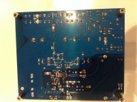
Can you post good quality pics of the troublesome PCB (top and bottom side)?
Hopefully the attached are ok...?
Still in denial about mounting C1 the wrong way but it's the most likely explanation.
Attachments
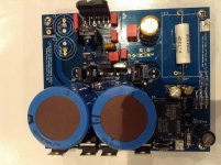
Hopefully the attached are ok...?
And the top.
Attachments
Nothing obviously wrong.
Just check that R11 is still good, it could have been burnt, on the photo it's not clear.
Just check that R11 is still good, it could have been burnt, on the photo it's not clear.
Nothing obviously wrong.
Just check that R11 is still good, it could have been burnt, on the photo it's not clear.
If you look closely it looks like one side of r11 is a dry solder connection.
Sent from my iPad using Tapatalk
- Home
- Amplifiers
- Chip Amps
- My_Ref Fremen Edition - Build thread and tutorial