after a few testing I found there is some dust behind the board which had faulty diode, did some dust cleaning,
Now the board only turns only when I turn off the power.
Now the board only turns only when I turn off the power.
okay just a few update
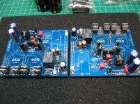
Board A (the one originally doe not have any problem) only LED turns on, LM3886 does heat up, output does have speaker sound, output measured 500mV with input OC/SC
Board B (replaced diode) LED turns on once it is powered down.
Board A (the one originally doe not have any problem) only LED turns on, LM3886 does heat up, output does have speaker sound, output measured 500mV with input OC/SC
Board B (replaced diode) LED turns on once it is powered down.
I am getting ready for starting my FE build and try to figure out what extra stuff i have to order. I have no training in electronics so I my knowledge is growing only slowly ;-)
From reading the build thread I figured that inrush current protections wouldn't be such a bad thing. CL-60 was mentioned. Sounds like an easy solution. Are there any drawbacks vs. using a current inrush PCB like offered in the diyaudio store?
Also - trying to figure out what fuses to use on primary and secondary side. I will use a 2x24V 120VA R-core. So for primary side 5A (I=120/24) as a max rating?
And for secondary I don't know how to calculate. Maybe 68W is max for 4 Ohms load. So 68/24=2,8?
Is that way of calculating it right or total nonsense? *ggg*
I realize that there was a fuse rating of 2.5 slow blow suggested but I really would like to know how to calculate that value ;-)
I am getting ready for starting my FE build and try to figure out what extra stuff i have to order. I have no training in electronics so I my knowledge is growing only slowly ;-)
From reading the build thread I figured that inrush current protections wouldn't be such a bad thing. CL-60 was mentioned. Sounds like an easy solution. Are there any drawbacks vs. using a current inrush PCB like offered in the diyaudio store?
Also - trying to figure out what fuses to use on primary and secondary side. I will use a 2x24V 120VA R-core. So for primary side 5A (I=120/24) as a max rating?
And for secondary I don't know how to calculate. Maybe 68W is max for 4 Ohms load. So 68/24=2,8?
Is that way of calculating it right or total nonsense? *ggg*
I realize that there was a fuse rating of 2.5 slow blow suggested but I really would like to know how to calculate that value ;-)
The way that I look at this is your output is 120VA @ 24V and you have 2 transformers. So, 120VA/24V = 5A. If you want to use a fuse on the secondaries, then a 5A slow blow should work. By the way, even though the chip could max out at 68W, the My_Ref variants including the FE are typically good for about 45W which is plenty for most speakers.
On the primary side, the current is multiplied by the output/input voltage ratio. If you have 120V mains, then 24V/120V*5A (output) = 1A input for 1 transformer.
I use a 3A slow blow on the input, but I am using 2 larger torriodal transformers in parallel. I don't use a secondary fuse. I also don't use any inrush current protection. I have used CL-60s on a Class A power amp but they use a lot of current right from switch "on" and have huge power supply capacitors. The FE only needs modest power supply capacitors, so I think there is less need for inrush current protection.
How about guys? Am I doing that right?
Last edited:
The Primary fuse for a transformer can be calculated for two methods of operation.
For use where no soft start is used to limit start up current
Mains fuse rating = 3* VA / Vac this gives 3*120/230 = 1.56Aac Use a T1.6A fuse.
If you wanted to use a current limiting soft start, then the Mains fuse rating is VA / Vac and for a 120VA 230Vac transformer this comes to 120/230 = 0.52A use a T500mA fuse. This is commonly referred to as close rating of the mains fuse.
The Fuse will pass a very short term overload current at least double that rating. For this example I'll allow a 1Amax overload current.
The 230Vac will try to push 1Amax through 230ohms of primary circuit resistance. The 120VA may have a primary resistance anywhere from 40ohms to 100ohms, I'll assume you measured 80ohms.
The added resistance of the soft start would be that 230ohms minus the 80ohms of primary winding leaving 150r of added resistor. Short this out with a bypass relay timed for a delay of approx 200ms.
For very small transformers most Builders would not consider the complexity of soft starting and just go straight to direct online starting with the 3times fuse rating.
Last edited:
Thank you Jac and Andrew. That was a great explanation!
The mains fuse is there primarily to prevent the transformer to go up in flames in case of a malfunction - right? Is this base covered with the 3x120 rule? In theory the secondary side could overload as well if not fused i guess... or am I being paranoid here? *g*
The mains fuse is there primarily to prevent the transformer to go up in flames in case of a malfunction - right? Is this base covered with the 3x120 rule? In theory the secondary side could overload as well if not fused i guess... or am I being paranoid here? *g*
Good to know. I thought safety earth does that. So this is in case someone touches the transformer wires in an open case?
let me rephrase my question: is the 3x rating sufficient for human safety?
let me rephrase my question: is the 3x rating sufficient for human safety?
If you have to ask those questions should you be playing with mains voltages? Not being negative, but 120vac can kill you.
That's why I'm asking before the build...
I appreciate your concern and I agree I have to learn a lot. Only way to do that is asking...
I appreciate your concern and I agree I have to learn a lot. Only way to do that is asking...
I use close rated fusing and I use soft starting for any transformer of 160VA and larger.
For very small transformer I use the 3times fuse rating.
I just opened up a small amplifier using a 135VA toroid.
It has a T1A as mains fuse.
But that does not stop you getting killed after you put your fingers in.
I also have ELCB (RCBO) on all my power rings except my listening room.That should stop people getting killed by sticking fingers into power sockets.
andrew: thanks again for clarifying 🙂
to be honest i didn't think about what I said *g* I shouldn't write posts on my phone while watching tv. All makes sense now, fuse is in case of short. In Austria probably every house (that is not waaaay old) has fi switches (rcbo) in case someone gets into the circuit. Still not a good idea to try out ;-)
to be honest i didn't think about what I said *g* I shouldn't write posts on my phone while watching tv. All makes sense now, fuse is in case of short. In Austria probably every house (that is not waaaay old) has fi switches (rcbo) in case someone gets into the circuit. Still not a good idea to try out ;-)
Last edited:
In Austria it should be 230 vac, not 120 vac. That is even more dangerous.andrew: thanks again for clarifying 🙂
to be honest i didn't think about what I said *g* I shouldn't write posts on my phone while watching tv. All makes sense now, fuse is in case of short. In Austria probably every house (that is not waaaay old) has fi switches (rcbo) in case someone gets into the circuit. Still not a good idea to try out ;-)
The suggested fuse for a dual mono My_Ref amp in a single cabinet are:
1.3A Slow-Blow (230V)
2.5A Slow-Blow (120V)
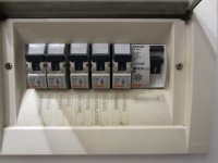
In any case in whole Europe each home has at least two magnethermic switches which cuts off when you reach a certain threshold for each circuit (10A and 16A usually) and at least a residual-current circuit breaker which cuts off when the difference from neutral and safety ground is bigger than 30mA.
This is my switchgear:

With such safety devices it's not so easy to be electrocuted, nevertheless we MUST take maximum care when dealing with AC, protections can fail... or be insufficent.
1.3A Slow-Blow (230V)
2.5A Slow-Blow (120V)
In any case in whole Europe each home has at least two magnethermic switches which cuts off when you reach a certain threshold for each circuit (10A and 16A usually) and at least a residual-current circuit breaker which cuts off when the difference from neutral and safety ground is bigger than 30mA.
This is my switchgear:
With such safety devices it's not so easy to be electrocuted, nevertheless we MUST take maximum care when dealing with AC, protections can fail... or be insufficent.
Attachments
thanks dario, these are the exactly breakers i tried to talk about 🙂 Again, thanks for all the concern. You are right its important to be careful.
troy - yes its 230
troy - yes its 230
I ordered the fremen fe and decided last minute to order the evo mod instead of the normal bom. So just to verify - C10 and R39 are left unpopulated?
And regarding (non electrolytic) capacitor orientation - the writing on the cap ends at the o ? Did i interpret that right?
And regarding (non electrolytic) capacitor orientation - the writing on the cap ends at the o ? Did i interpret that right?
I ordered the fremen fe and decided last minute to order the evo mod instead of the normal bom. So just to verify - C10 and R39 are left unpopulated?
Yes
And regarding (non electrolytic) capacitor orientation - the writing on the cap ends at the o ? Did i interpret that right?
It's usually so but for Wimas pay attention, some of them have markings on the 'wrong' side.
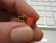
All Wimas have a small sign, the small ones on one side, the bigger on front/back:
That sign should be on the left side (small) or front (big), otherwise markings are reversed.
The one in the pic is reversed.
Attachments
xcj999, BTW you should have Amtrans, isnt'it?
Amtrans seems to be marked consistently, markings goes on the side with the 'o', like straight Wimas
Amtrans seems to be marked consistently, markings goes on the side with the 'o', like straight Wimas
- Home
- Amplifiers
- Chip Amps
- My_Ref Fremen Edition - Build thread and tutorial