Hi Nick,
Resistors are here....
Kiwame | Hifi Collective
And the caps are oscons here
Oscon Capacitors | Mouser
Resistors are here....
Kiwame | Hifi Collective
And the caps are oscons here
Oscon Capacitors | Mouser
Looks like Mouser have stopped doing the 5w KOA Speer (Kiwame) resistors. Shame, they were approx 70% cheaper than they price Hifi Collective are charging for them!
FWIW, Kiwame resistors are not available in Japan but KOA SPR are and it is the same product.
"Kiwame' is an exotic name dreamt up to extract a premium from audiophiles. See this post:
http://www.diyaudio.com/forums/tubes-valves/116634-kiwame-resistors.html
"Kiwame' is an exotic name dreamt up to extract a premium from audiophiles. See this post:
http://www.diyaudio.com/forums/tubes-valves/116634-kiwame-resistors.html
All you ever need to know about digital audio!
This is very interesting! Please view the whole video! It explains very clearly, why 24/96 audio is identical to 16/44 audio. And further more: A DAC which produces perfect rectangle signals at the output has a construction fault!
Regards Ralf
Xiph.Org Video Presentations: Digital Show & Tell
24/192 Music Downloads are Very Silly Indeed
Ok, even though I don't have a DDDAC and don't plan to get one, I've been following this thread for sometime as it has some great information on DAC upgrades that have wider applications.
But this summer I got a Sony HAP-Z1ES with the thought molest it with some Vinnie Rossi-inspired mods.
And old and slow guy that I am, I JUST REALIZED that the PCM1795 used in the HAPZ is likely just an updated PCM1794! After spending sometime comparing the datasheets, this seems to be very true. So MANY of the mods you've done to optimize your single-board PCM1794 DACs also apply here. Specifically, I see the following mods that will probably transfer over to the PCM1795 setup in the HAPZ very nicely:
- Analog 8VDC power supply
- Pin 20 CCS
- Passive I/V using high-quality resistors (likely Susumu)
- JFET Buffer after the I/V
- Cinemag transformers as output transformers
- Cinemag Loading
As for the other mods, I've already done a number of power-supply-related mods on the HAPZ including replacing the somewhat pedestrian regulators with higher-quality ones including ADM715x-based ones from Acko for the clocks, the DACs' digital and analog sides.
I also did some part upgrades on the existing output stages, but I didn't go too far here as I planned to replace them entirely anyway. Your Passive I/V->JFET Buffer->Cinemag sounds perfect!!!!
One thing I don't think applies to the HAPZ is the 1/2 clock delay, partly because the Sony uses I2S instead of Right-Justified digital input and partly because it already includes a clock divider circuit which I suspect does introduce some delay already.
So I've sent PMs to both Enrico and Carlsor asking about mod boards & parts.
And there is already a HAPZ mod thread where I've discussed what I've done so far, so I post there and won't litter this thread with any details except where I have specific questions about what you've done.
And finally, if any of you know that there are larger differences between the PCM1794 and PCM1795 that I have not recognized that make your mods not valid, please let me know. I did search and saw that the PCM1795 was mentioned a few times on the main DDDAC thread during discussion of the DDDAC technical details, so that adds a bit of credibility to my plan.
THANKS for all the great info on this thread and bearing with me for a few 'dumb-question' posts.
Greg in Mississippi
Hi all,
First, I would like to thank everyone who has helped improving the DDDAC and a special thanks to Doede for his design.
I read extensively pages and pages of topics like this either here on diyAudio and pinkfishmedia for a year or so.
The current project is to modify Doede's DAC to adapt some other components to improve the DDDAC. I want to incorporate upgrades mentioned in this topic, I understood the modifications but I lack of some more explanations on the way to go on the final power supply arrangements on DAC boards, especially caps in the power supplies (2 x 100uF 25V Elna Silmic II in // to filter one 12V power supply for the 8v line and only one 47uF 20V Oscon on an other 12V for the 3.3v line?). I can use other PCB footprints so I can adapt to lager caps if necessary.
The main goal here is to modify the global schematic and design nice PCBs including improvements and little more space for components to build myself a great DAC for my system. If anyone is interested just say so and I could order some more PCBs and post them to whoever wants some.
Thanks for the help.
Corentin
Last edited:
Hi,
I was starting to think I might include DAC board into the main board since the buffer allows use of one DAC board with Cinemag transfos. I would keep the idea of stacking boards but just include one directly on the main board.
Would it be wise to you to include one DAC board to the main board? Or continue with Doede's separated design?
Thanks.
Corentin
Hi, amazing thread guys! Almost too much info to digest for a electronical noob like me...
Couple of questions regarding the DDDAC, hope someone can help me.
Somewhere on this forum I read about a revised version of the board, is this true/when is it available? What will change?
Somewhere this year I like to build a DDDAC 1794, but according to this forum CCS and a buffer output stage are essential. Or instead of buffer invest in a analoge 8VDC supply? Does somebody still sell those kits or a spare one? I'm certainly not experienced enough to build them myself from scrap...
Thanks,
Wilco
The new dac boards are probably a couple of months away. I'm fairly sure they will come with Tent shunts on the analogue side and CCS.
Audio creative should sell all you need.
DDDAC 1794 - DIY DAC Archives - Audio Creative Shop
Good luck !!
Audio creative should sell all you need.
DDDAC 1794 - DIY DAC Archives - Audio Creative Shop
Good luck !!
Hi all,
First, I would like to thank everyone who has helped improving the DDDAC and a special thanks to Doede for his design.
I read extensively pages and pages of topics like this either here on diyAudio and pinkfishmedia for a year or so.
The current project is to modify Doede's DAC to adapt some other components to improve the DDDAC. I want to incorporate upgrades mentioned in this topic, I understood the modifications but I lack of some more explanations on the way to go on the final power supply arrangements on DAC boards, especially caps in the power supplies (2 x 100uF 25V Elna Silmic II in // to filter one 12V power supply for the 8v line and only one 47uF 20V Oscon on an other 12V for the 3.3v line?). I can use other PCB footprints so I can adapt to lager caps if necessary.
The main goal here is to modify the global schematic and design nice PCBs including improvements and little more space for components to build myself a great DAC for my system. If anyone is interested just say so and I could order some more PCBs and post them to whoever wants some.
Thanks for the help.
Corentin
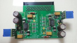
Maybe something like that ? 😀
Attachments

Thanx, just bought a cheaper diy DAC I heard a lot about on dutch audio forum. Maybe I will build the new boards to compare them...

All the above was not possible without the amazing synergy and team work between Ross (carlsors) Frankie (palmito) and myself.
Thanks guys, we did a fantastic great Team job !!!
And of course thanks to the amazing design of Doede Douma
Thanks guys, we did a fantastic great Team job !!!
And of course thanks to the amazing design of Doede Douma
All the above was not possible without the amazing synergy and team work between Ross (carlsors) Frankie (palmito) and myself.
Thanks guys, we did a fantastic great Team job !!!
And of course thanks to the amazing design of Doede Douma
excellent work and congratulation to all of you 3 guys 🙂
maybe you could share some details and your findings regarding your new dac boards, especially the on-board psu, used caps, etc.
looking forward to reading your review and comparison of the sound quality to your first version ( with the integrated buffer)
best wishes and cheers,
m.
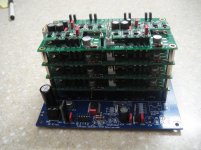
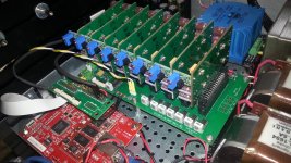
Or like that?... 😀😀😀
The 8 board is my beloved DAC
Nice work
Bet its a good improvement on the stock version
Wish I was good at circuit board design
Have you tried taking out the resistors on the i2s lines?
excellent work and congratulation to all of you 3 guys 🙂
maybe you could share some details and your findings regarding your new dac boards, especially the on-board psu, used caps, etc.
looking forward to reading your review and comparison of the sound quality to your first version ( with the integrated buffer)
best wishes and cheers,
m.
Hi mr_whocares,
During the design of the dac board with buffer there was 2 main thinks that I didn't like: the boards installed on top of each other and the size (and cost) of the Tent shunts.
The main drawbacks of the boards installed horizontally:
- The size of the enclosure. If you want a dac with 8 boards you have to design a dedicated enclosure
- The troubleshooting/maintenance. With the boards connected all together if you have a fault in one of the boards you have a BIG problem. During our design I used the Samtec pins to be able to mount/dismount the boards for make our measurements and test
- The heat dissipation of the Tent shunts. I was obliged to make 4 holes under each shunt to dissipate the heat but I never was really confident even if I play with 4 stacked boards for months.
The main drawbacks of the Tents shunts:
- The size. They are big and they need a proper room
- The cost. They cost (I go by memory) raffly 35 USD each and we need 4 for each board. For a 4 board they cost +/- 600 USD
- The PSU. To make the shunt to work properly you need a BIG PSU. I realized in my first DAC with 4 boards the one suggested by supersurfer with the 2 Lundalh choke and a big trafo. The PSU and the shunts work really well but what about if I want to go for 8 boards?
- The heat. As I mentioned above the heat should be taken in consideration.
- The delivery time. Well, this was maybe only my experience but at that time I wait more than 2 months to have my order delivered. It's not a complain but it's anyway something to take in consideration
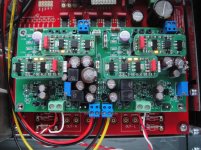
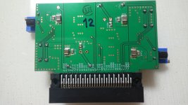
So, to solve the above the only way is to redesign the motherboard as a "bus" in order to install the DAC boards vertically and we solved the above issues...
- The enclosure can be a standard 3U even with 8 boards
- We can pull out the boards at any time without desoldering anything. We can also test the DAC boards one by one before to install in the motherboard.
- The Tents are now vertical and free so they can dissipate much easily. Yes, the first trial of the vertical DAC boards was still with the Tent shunts.
Redesigning the motherboard permit also to review the PSU distribution and now we have the chance to separate the digital and analogic power supply (both POSITIVE and GND) with just 4 pins selectors and have been added the UFL connectors for the I2S, no more adapters to connect to the various sources.
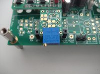
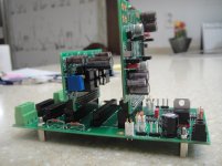
Now the new DAC board... There are nowadays many fancy LDOs available in the market and Linear is renowned to design extremely good chips. Looking in the PCM D/S the choice was the LT1762, a low noise LDO 20µVRMS with Voltage regulation through resistors and an output current of 150 mA. The board design follow the D/S recommendation regarding the in and out caps and distance of the caps from the chip pins (as you can see in the pictures there decoupling caps in both side of the board).
The result is simply perfect 🙂 With the LDOs all the above "issues" have been solved and I don't miss at all the Tents 😀
My family is waiting me for go dinner... I will be back tomorrow with some other info and pictures
Best Regards,
Enrico
Nice work
Bet its a good improvement on the stock version
Wish I was good at circuit board design
Have you tried taking out the resistors on the i2s lines?
Yes indeed!!
No, I never try taking out the resistors... the DAC is playing so well and I am so busy with other thinks that I will not try, at least in the next months
Regards,
Enrico
- Home
- Source & Line
- Digital Line Level
- Upgraded Single Board PCM1794 NOS DDDAC